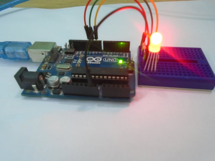
In this tutorial, you will learn about Arduino RGB led interfacing. The RGB led consists of three different led’s, from the name you can guess that these led’s are red, green and blue. We can obtain many other colors by mixing up these colors. The Arduino has a analog write function which will help us in obtaining different colors for Arduino RGB led.
For Custom Projects, hire me at https://www.freelancer.com/u/Muhammadaqibdutt
RGB LED SchematicThere are actually two types of RGB led’s; the common cathode one and the common anode one. In the common cathode RGB led, the cathode of all the led’s is common and we give PWM signals to the anode of led’s while in the common anode RGB led, the anode of all the led’s is common and we give PWM signals to the cathode of led’s.
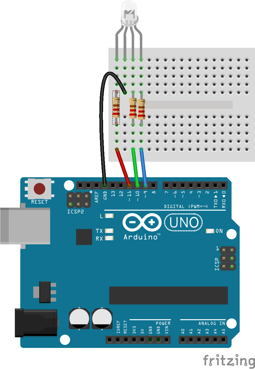
The one that we are going to use is the common cathode RGB led. So, we will connect the common pin to the GND of Arduino and the other three leads of the led’s to the PWM pins of Arduino.
Note
You cannot distinguish between the common cathode and common anode type by just looking at the RGB led because both look same. You will have to make the connections to see that either it is common cathode or common anode.
The RGB led has one big lead than the other leads. In the common cathode case, it will be connected to GND and in the common anode case; it will be connected to 5V.
Connect the cathode of the RGB led which is the longer pin of RGB led to the GND of Arduino and the other three pins to the pin 11, 10, 9 of Arduino through the 220 ohm resistors. The resistors will prevent the excess amount of current to flow through the RGB led.
If you are using the common anode RGB led, then connect the long lead to the 5V of Arduino.
Note
If you have any other Arduino, then make sure that you are using the PWM pins of that Arduino. The PWM pins have a ~ sign with them.
WorkingInside the RGB led, there are three more led’s. So by changing the brightness of these led’s, we can obtain many other colors. To change brightness of RGB led, we can use the PWM pins of Arduino. The PWM pins will give signal different duty cycles to the RGB led to obtain different colors.
The below RGB color wheel will help you in selecting different colors for Arduino RGB led.
Codeint red_light_pin= 11;
int green_light_pin = 10;
int blue_light_pin = 9;
void setup() {
pinMode(red_light_pin, OUTPUT);
pinMode(green_light_pin, OUTPUT);
pinMode(blue_light_pin, OUTPUT);
}
void loop() {
RGB_color(255, 0, 0); // Red
delay(1000);
RGB_color(0, 255, 0); // Green
delay(1000);
RGB_color(0, 0, 255); // Blue
delay(1000);
RGB_color(255, 255, 125); // Raspberry
delay(1000);
RGB_color(0, 255, 255); // Cyan
delay(1000);
RGB_color(255, 0, 255); // Magenta
delay(1000);
RGB_color(255, 255, 0); // Yellow
delay(1000);
RGB_color(255, 255, 255); // White
delay(1000);
}
void RGB_color(int red_light_value, int green_light_value, int blue_light_value)
{
analogWrite(red_light_pin, red_light_value);
analogWrite(green_light_pin, green_light_value);
analogWrite(blue_light_pin, blue_light_value);
}If you have any comments, then feel free to ask in the comment section.


_ztBMuBhMHo.jpg?auto=compress%2Cformat&w=48&h=48&fit=fill&bg=ffffff)


Comments