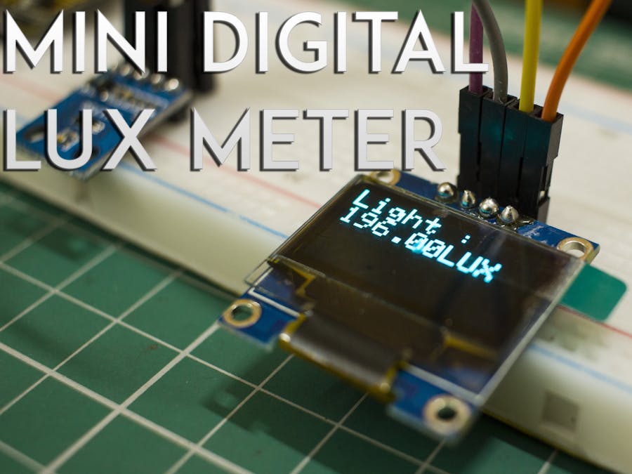
A digital Lux Meter is a device to measure the intensity of a source of light. A lux meter will be used in photography to estimate how bright the flash is and also the encircling ambient lighting.
working principle of lux meter :
working principle of lux meter :Most of the lux meter consists of a body, photocell or light sensor, and display. The light that falls on to the photocell or sensor contains energy that is transformed into electric current. Indeed, the measure of current depends on the light that strokes the photocell or light sensor. Lux meters read the electrical current calculate the appropriate value, and show this value on its display.
Step 1: Components Needed- NodeMCU
- BH1750 light intensity module
- OLED 0.96 inch I2C IIC Interface OLED Screen Display 4 Pin (White)
- breadboard
- jumper wires
BH1750 is a digital ambient light sensor that is used commonly used in mobile phones to
manage screen brightness based on the environment lighting. This sensor can accurately measure the LUX value of light up to 65535lx.
Features of the sensor:
● Power Supply: 2.4V-3.6V (typically 3.0V)
● Less current consumption: 0.12mA
● Measuring Range: 1-65535lx
● Communication: I2C bus
● Built-in A/D converter for converting analog illuminance in the digital data.
● A very small effect of IR radiation
● Highly responsive near to the human eye.
This is a BH1750 light intensity sensor breakout board with a 16 bit AD converter built-inwhich can immediately output a digital signal, there is no need for complex calculations. This is more accurate and simpler to use the version of the simple LDR which only outputs a voltage that needs to be calculated to obtain meaningful data.
Board Schematic
● J1 is interfacing connector
● U1 is a voltage regulator which gives out 3V to board from 3.3-5V supply input
● Q1 is bidirectional data level translator for 5V to 3V level conversion
● D1 is unidirectional clock level translator for 5V to 3V level conversion
● Please note that the "addr" Pin is to assign a different I2C address to the sensor.
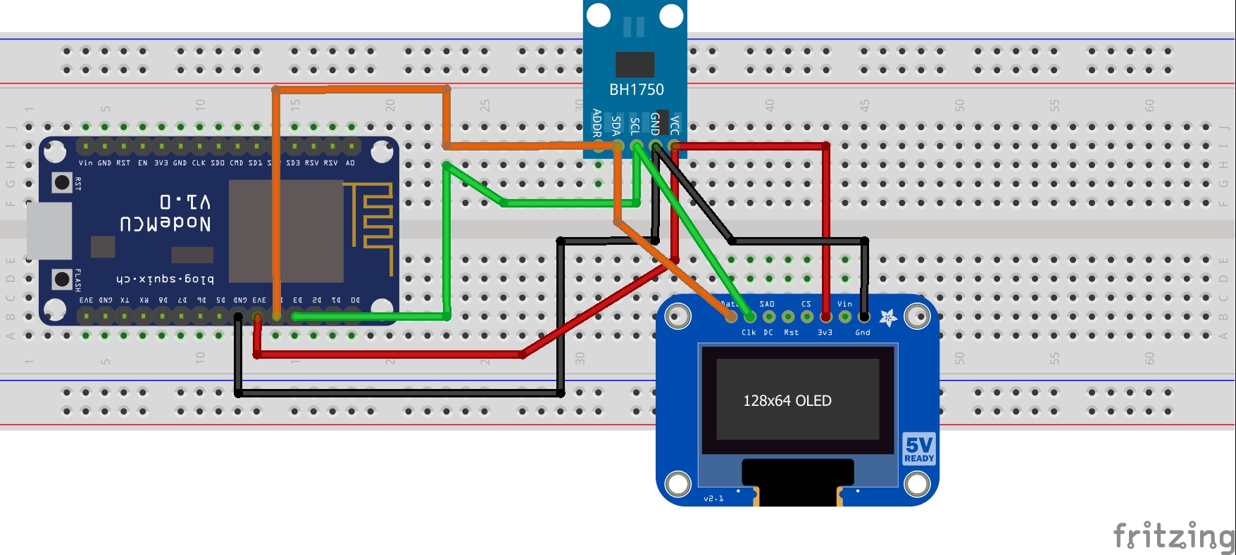
Step 3: Circuit DiagramFirst, connect the VCC and GND of the BH1750 Light Sensor to 3V3 and GND of ESP 8266 Then connect the SCL and SDA pins of the sensor to corresponding pins of ESp 8266 using jumper wires.
Then, connect the SCL, SDA, GND, and VCC pin of the OLED display to the corresponding BH1750 sensor pins.
Let's talk about lux and Illuminance:
The lux (symbol: lx) is the SI derived unit of illuminance, measuring luminous flux per unitarea. It is equal to one lumen per square meter. In photometry, this is used as a measure of the intensity, as perceived by the human eye, of light that hits or passes through a surface. It is analogous to the radiometric unit watt per square meter, but with the power at each wavelength weighted according to the luminosity function, a standardized model of human visual brightness perception. In English, "lux" is used as both the singular and plural form.
Illuminance: Illuminance is a measure of how much luminous flux is spread over a given area. One can think of luminous flux (measured in lumens) as a measure of the total "amount" of visible light present, and the illuminance as a measure of the intensity of illumination on a surface. A given amount of light will illuminate a surface more dimly if it is spread over a larger area, so illuminance is inversely proportional to the area when the luminous flux is held constant.
One lux is equal to one lumen per square metre:
1 lx = 1 lm/m2 = 1 cd·sr/m2.
A flux of 1000 lumens, concentrated into an area of 1 square meter, lights up that square meter with an illuminance of 1000 lux. However, the same 1000 lumens, spread out over 10 square meters produces a dimmer illuminance of only 100 lux.
Step 4: Lets CodeDownload the libraries :
We can download libraries in the Arduino IDE
steps :
Sketch -> Include libraries -> manage libraries
For this project library needed:
- Adafruit ESP8266
- Adafruit SSD1306
- BH1750FVI


Comments
Please log in or sign up to comment.