


Hardware components | ||||||
| × | 1 | ||||
| × | 1 | ||||
 |
| × | 1 | |||
| × | 3 | ||||
 |
| × | 1 | |||
 |
| × | 1 | |||
| × | 2 | ||||
Software apps and online services | ||||||
 |
| |||||
The Blinky Bike project is an ultimate solution to add light system to any Bike, ( and electric Bike) using a 5V power bank or the bike Battery. It relies on NeoPixel LEDs (WS8212) flexible stripes. The system based on an Atmel ATTiny 85 micro-controller, allows different light modes that can be selected using two water proof switches (One for the Left hand and one for the Right hand).
Device UsageThe device Left and Right buttons are the only interface with the system allowing to :
- Turn ON and OFF the light system
- Turn Left and Right indicator
Switches operations are :
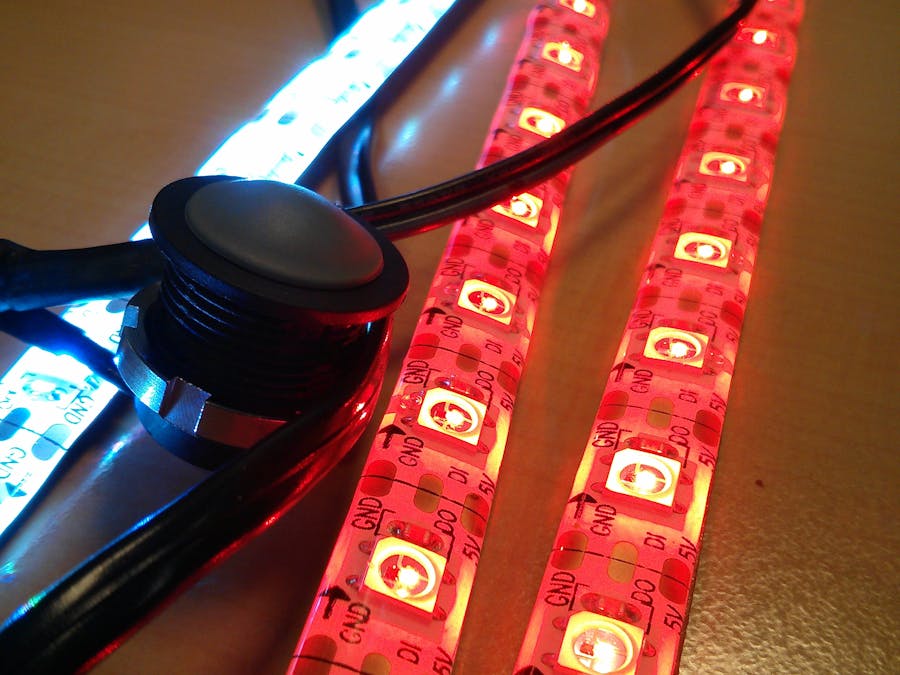
The system is based on a Front LED flexible stripe and two Rear LED Flexible Stripe, one for the Left and one for the Right indicator.
The Front and Rear LEDs stripes are composed of a total of 30 LEDs, 8 for the Front and 11 for each Rear stripes.
The system is designed to be power friendly with the e-Bike battery, as the battery might not be able to provide the full power required to have all the LEDs turned on at the same time. As the NeoPixel RGB LEDs (WS8212) consumes 20 mA per color channel, with a total of 60 mA (3 channels * 20 mA) when the LED is turned full bright White color (Red = 255, Green = 255, Blue = 255). The challenge is to not be over 500 mA (power limit supplied by the Battery on my e-Bike). I have applied a secure level set to 450 mA maximum. Leading then to a limit of 7 LEDs active at a time.
Having only 7 LEDs is really limitating for a bike light system, so the solution is to multiplex the LEDs and ensure that only those 7 LEDs are on, while all the others are off. If the multiplexing switch is performed fast enough, it should be possible to make it not visible for a Human eye.
Therefore, the ATTiny firmware is taking care of the current limitation by switching on and off the LEDs, remaining only 7 LEDs on at a time, giving a maximum power consumption for the LEDs of 420 mA.
This can be adjusted by editing the /BlinkyBike/BlinkyBike/Stripes.h file :
// Number of LED
#define LED_STRIPE_FRONT_ON   3
#define LED_STRIPE_REAR_ON    2
When riding a bike at night, having fix light color is not the optimal solution to be visible by drivers. Therefore having some flashing, blinking mode for the lights gives more visibility. When light is On, the Front stripe displays a fast blinking animation at a frequency of 10 Hz or so.
When turning left or right, the visual animation is orange and blinky.
So having a flexible software architecture is a must have. With AnimationStep and Animation it is fairly simple to describe an animation.
The types are described as following :
struct AnimationStepFront
{
	unsigned long StepDuration;	// Step Duration in ms
	PixelColor Pixels[1];		// Step Pixels color
};
struct AnimationFront
{
	AnimationStepFront *animationStep;	// Front Step
	AnimationFront *nextAnimation;		// Next Front animation
};
And an animation is described as following :
AnimationStepFront stepWhiteFront = { 150,
{
	COLOR_PIXEL(WHITE)
}
};
AnimationStepFront stepBlackFront = { 50,
{
	COLOR_PIXEL(BLACK)
}
};
/* Animations for Front */
AnimationFront animationFrontOff = { &stepBlackFront, &animationFrontOff };
AnimationFront animationFrontOn = { &stepWhiteFront, &animationFrontOn };
The hardware is minimalistic as the Neopixel and ATTiny are embedding all the discrete components that you normally use to drive RGB LED.
The BlinkyBike system is built using the following hardware :
- AtTiny85
- 1 x 8 NeoPixel LEDs Stripe
- 2 x 11 NeoPixel LEDs Stripe
- 3 x 380 Ohms resistor
- 1 x 10 kOhms resistor
- 1 x 1000 µF capacitor
- 2 x water proof switches
You won't find any PCB layout, as I'm using through hole prototyping board, developed with Fritzing software.
The ATTiny 85 is a really cool Micro Controller that have 8 KB of Flash and 512 B of RAM to run any kind of C or C++ software. This gives some space to run a simple software and for this reason some optimization are required.
The project has been developed in C++ (C++11) in order to reuse and give more flexibility in case of development of new features. It is required to use the VisualMicro extension for Visual Studio 2013 in order to build the project.
AdaFruit is providing a library to drive the Neopixel devices, that you can directly integrate in your Arduino IDE. But this code has been designed to support various modes in order to address major use cases. The source code repository is containing an optimized version that works only with the Neopixels that I have selected and might not work if you choose a different one.
The Neopixel device requires specific timings that can't be reach when using the ATTiny 85 in 4 MHz (its default configuration) and therefore requires to use the 8 MHz mode. So it is mandatory to burn the correct fuses in the ATTIny before deploying the firmware. This can be done from the Arduino IDE by selecting the ATTiny 85 target and selecting the clock frequency to 8 MHz (internal).
GalleryVideo
Pictures


Comments
Please log in or sign up to comment.