


Hardware components | ||||||
 |
| × | 1 | |||
 |
| × | 1 | |||
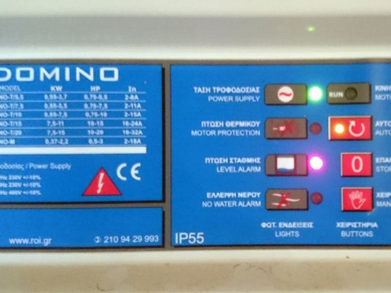
Oh well someone has to watch over our sewage pump. Which has already a panel that control when to start / stop the pump or when to turn on heat protection when there’s no “water” left.
The problem was that this control panel is two floors down and if we wanted to check its condition (i.e. after a power failure or if the pump has stopped for heat protection) we should make regular passes from the basement.
The good thing about this control panel is that it has its own LEDs showing the status of the pump (Power Supply, Motor On, Motor Protection, Automatic (on/off), Level Alarm and No Water Alarm).
Enter esp8266 / NodeMCU.
With the use of six photoresistors (CdS, LDR) we can read the status of each LED of the control panel and output its status on a web page. Yippee..
The schematics on how to connect LDRs to an esp8266 or a NodeMCU are all over the web if you look. For three LDRs for example is the following:
In the code I’m reading the digital output of each LDR as 0 or 1.
Putting the six LDRs in the correct positions was easy on a 9x15cm prototyping PCB (luckily 9cm was the height of the opening of the control panel).
Reversing the PCB and placing it over the control panel with a breadboard to hold the NodeMCU for testing:
there was some duct tape involved.. (Duct tape is for everything right?)
Aaand we have our output readings in a static IP in our network (where green color is good):
In the code of the NodeMCU (with Arduino IDE) there is also a part that connects with IFTTT Maker channel to notify me for important events.
:)


Comments
Please log in or sign up to comment.