


Hardware components | ||||||
 |
| × | 1 | |||
| × | 1 | ||||
| × | 2 | ||||
| × | 1 | ||||
| × | 1 | ||||
 |
| × | 1 | |||
| × | 1 | ||||
Software apps and online services | ||||||
| ||||||
This project comes from a common need we have in our maker space: we are a 24-hour facility, however we have serious, expensive equipment that requires a class and authorization to use. We cannot have someone present 24 hours a day to monitor the equipment, and rely on a punch card system currently to determine whether or not a particular member has taken a class/is authorized to use a piece of equipment.
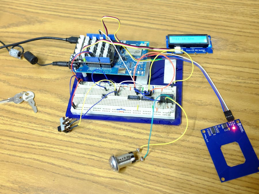
Having already built an RFID access control system for our front door, I decided to extend the same system to be able to interface with as many of the machines in our space as possible.
RequirementsThe requirements were:
- uses the same 125kHz tags that our front door system uses
- uses the same back end database
- has one design that could interface with as many machines as possible
- is electrically isolated from those machines as to not affect their normal use
The key issue I ran into was not how to determine whether a particular user was or was not allowed to use a particular machine, rather it was how to have an electrically isolated device that would not accidentally turn the machine off mid use.
My original idea for this solution was to use a current sensing device; the idea being that after the initial authorization for a machine, my device would not disable the machine until its current draw dropped below a certain level. While interesting, this ended up being problematic as some of the machines (particularly the 3D printers) drop into a low power mode at times giving false 'off' readings.
While I could spend time calibrating each device to the current draw patterns of each machine, I decided to instead use a latching circuit from a MUX and an OR gate:
The button on the top right represents the enable line which is controlled by Edison, the middle button is the switch physically on the machine, the bottom MUX is really supposed to be a 5V relay (no relay component in Logisim), and the LED on the far right indicated whether the machine is on or off.
When the enable is held high, the switch may turn the machine on, and the machine will stay on until the switch is turned off (even if the enable is de-asserted). Once off, the machine will not turn back on until the enable is again held high.
Attaching to a machineTo attach to a machine, take the wires that originally connect the machine to its built-in on switch and cut it. This original switch is then wired into the middle button on my circuit, and the output (bottom right, MUX in the diagram, relay in the actual circuit) is wired to the leads from the machine that used to go to the switch.


Comments
Please log in or sign up to comment.