//**************************************************************//
//  Name    : shiftIn Example 1.2                               //
//  Author  : Carlyn Maw                                        //
//  Date    : 25 Jan, 2007                                      //
//  Version : 1.0                                               //
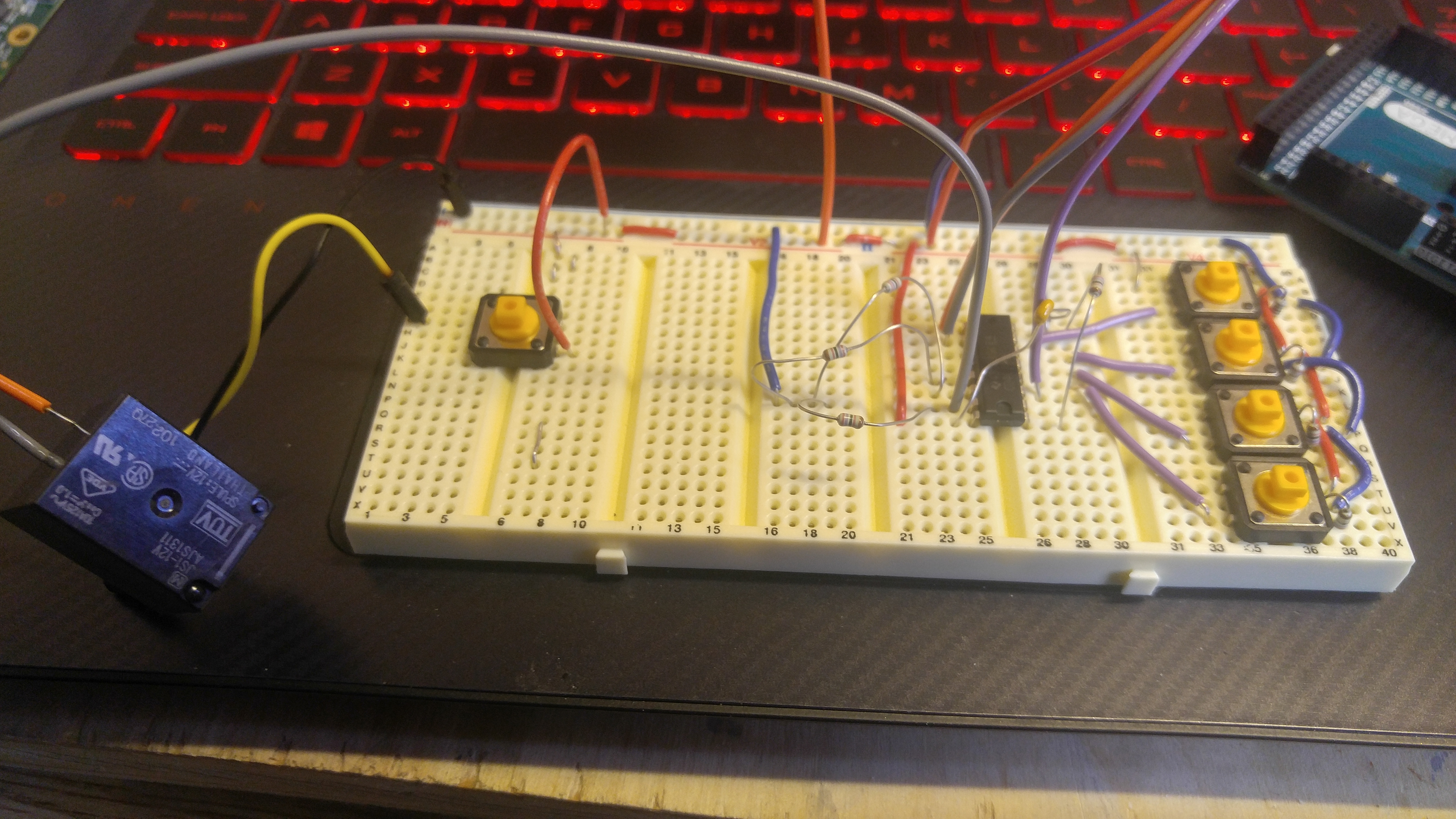
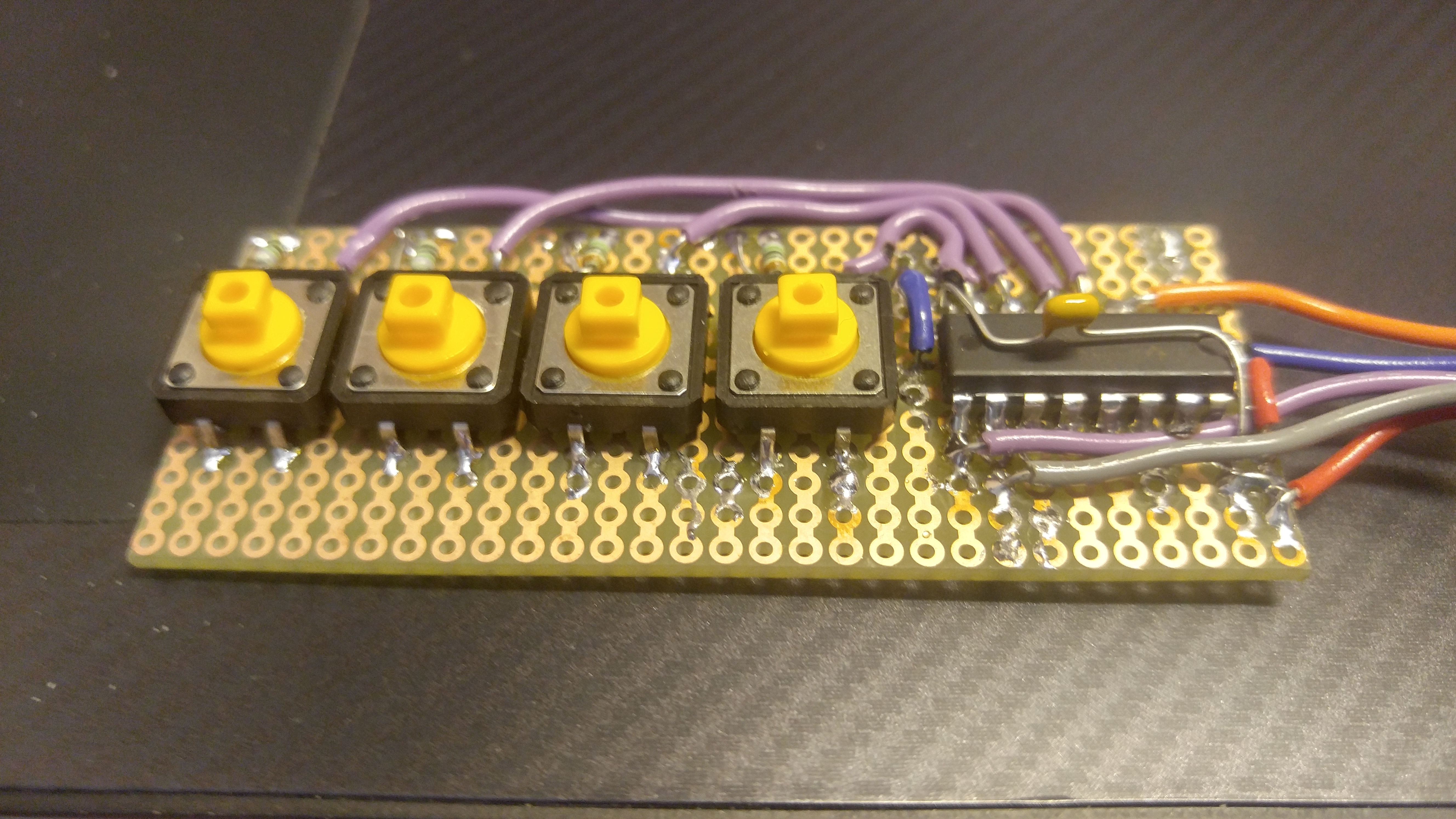
//  Notes   : Code for using a CD4021B Shift Register       //
//          :                                                   //
//****************************************************************

//define where your pins are
int latchPin = 8;
int dataPin = 9;
int clockPin = 7;

//Define variables to hold the data
//for shift register.
//starting with a non-zero numbers can help
//troubleshoot
byte switchVar1 = 72;  //01001000

//define an array that corresponds to values for each
//of the shift register's pins
char note2sing[] = {
  'C', 'd', 'e', 'f', 'g', 'a', 'b', 'c'};


void setup() {
  //start serial
  Serial.begin(9600);

  //define pin modes
  pinMode(latchPin, OUTPUT);
  pinMode(clockPin, OUTPUT);
  pinMode(dataPin, INPUT);

}

void loop() {

  //Pulse the latch pin:
  //set it to 1 to collect parallel data
  digitalWrite(latchPin,1);
  //set it to 1 to collect parallel data, wait
  delayMicroseconds(20);
  //set it to 0 to transmit data serially
  digitalWrite(latchPin,0);

  //while the shift register is in serial mode
  //collect each shift register into a byte
  //the register attached to the chip comes in first
  switchVar1 = shiftIn(dataPin, clockPin);

  //Print out the results.
  //leading 0's at the top of the byte
  //(7, 6, 5, etc) will be dropped before
  //the first pin that has a high input
  //reading
  Serial.println(switchVar1, BIN);


  //This for-loop steps through the byte
  //bit by bit which holds the shift register data
  //and if it was high (1) then it prints
  //the corresponding location in the array
  for (int n=0; n<=7; n++)
  {
    //so, when n is 3, it compares the bits
    //in switchVar1 and the binary number 00001000
    //which will only return true if there is a
    //1 in that bit (ie that pin) from the shift
    //register.
    if (switchVar1 & (1 << n) ){
      //print the value of the array location
      Serial.println(note2sing[n]);
    }
  }

//white space
Serial.println("-------------------");
//delay so all these print satements can keep up.
delay(500);

}

//------------------------------------------------end main loop

////// ----------------------------------------shiftIn function
///// just needs the location of the data pin and the clock pin
///// it returns a byte with each bit in the byte corresponding
///// to a pin on the shift register. leftBit 7 = Pin 7 / Bit 0= Pin 0

byte shiftIn(int myDataPin, int myClockPin) {
  int i;
  int temp = 0;
  int pinState;
  byte myDataIn = 0;

  pinMode(myClockPin, OUTPUT);
  pinMode(myDataPin, INPUT);
//we will be holding the clock pin high 8 times (0,..,7) at the
//end of each time through the for loop

//at the begining of each loop when we set the clock low, it will
//be doing the necessary low to high drop to cause the shift
//register's DataPin to change state based on the value
//of the next bit in its serial information flow.
//The register transmits the information about the pins from pin 7 to pin 0
//so that is why our function counts down
  for (i=7; i>=0; i--)
  {
    digitalWrite(myClockPin, 0);
    delayMicroseconds(0.2);
    temp = digitalRead(myDataPin);
    if (temp) {
      pinState = 1;
      //set the bit to 0 no matter what
      myDataIn = myDataIn | (1 << i);
    }
    else {
      //turn it off -- only necessary for debuging
     //print statement since myDataIn starts as 0
      pinState = 0;
    }

    //Debuging print statements
    //Serial.print(pinState);
    //Serial.print("     ");
    //Serial.println (dataIn, BIN);

    digitalWrite(myClockPin, 1);

  }
  //debuging print statements whitespace
  //Serial.println();
  //Serial.println(myDataIn, BIN);
  return myDataIn;
}


Comments