in the world of arduino it can happen, sooner or later, to have to deal with a dc motor. As you can imagine, arduino is unable to directly control a DC motor, as the latter requires high energy to operate.
Let's assume we are using the DC motor of a PC fan: to work it requires a 12V power supply with a current of about 50mA, for a total of 0.6W of power.
If we tried to control the motor with arduino, we must consider that the output power is 5V with a current of 40mA (max I / O out current), for a total of 0.2W at the output. So you see that energy is not enough!
Usually, to control a DC motor with arduino we use the H bridges, which allow us to increase the power supply of the motor through a separate circuit. A typical H bridge used for this purpose is the L293B.
But if we don't have an H bridge available, can we still control a DC motor with an arduino?
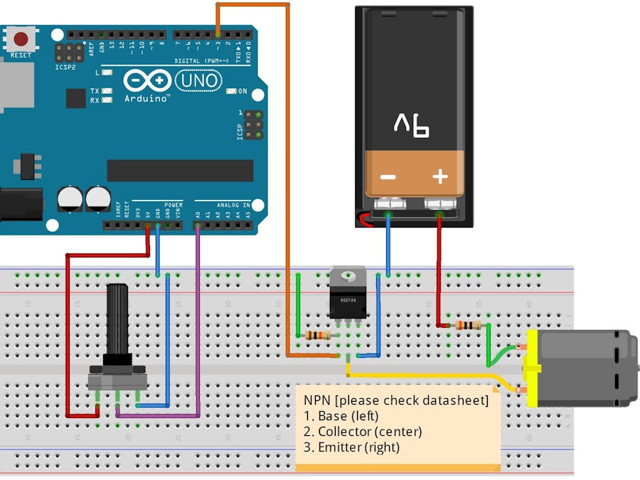
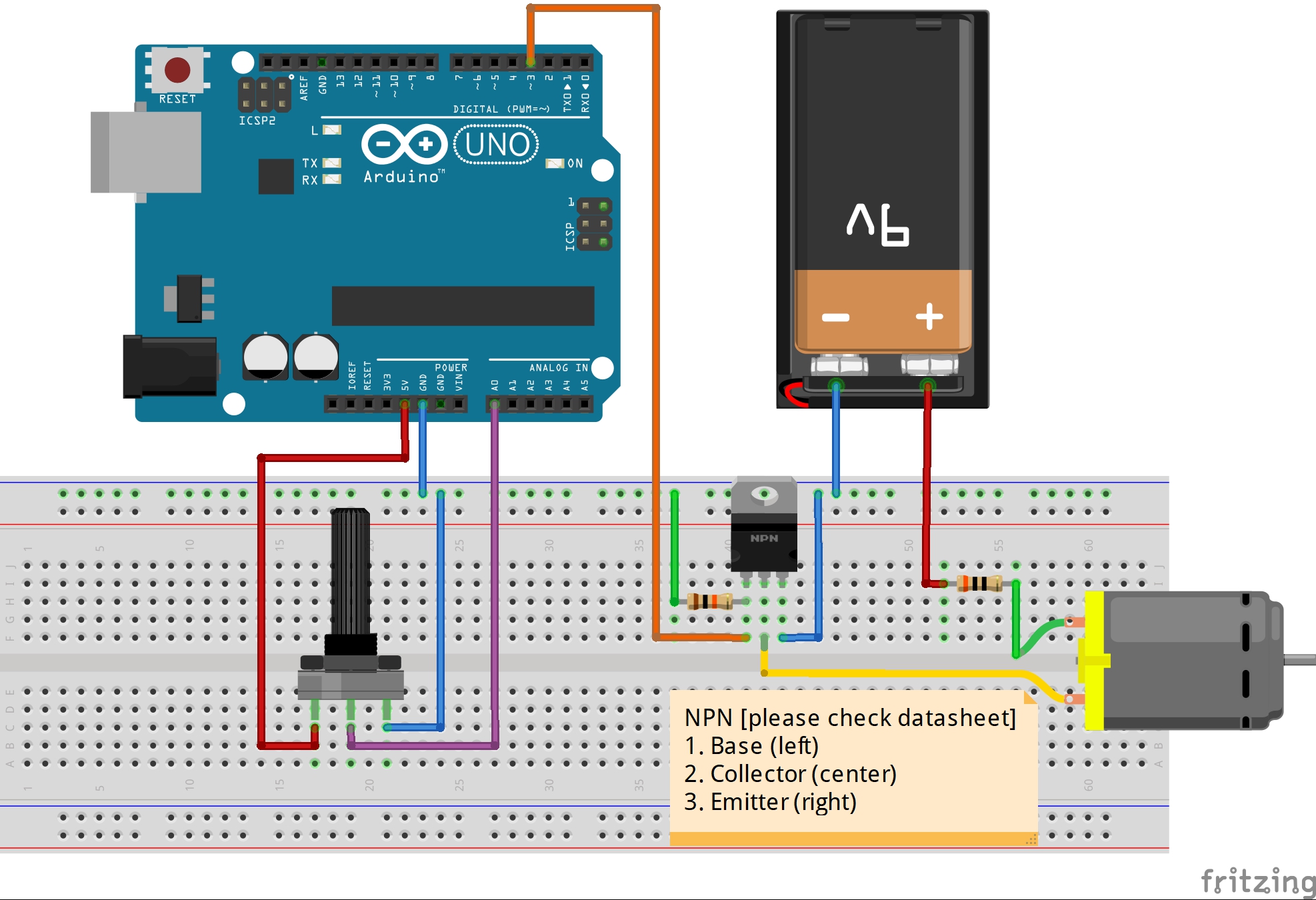
The answer of course is yes! Using an NPN transistor, whose connections are given respectively by the pairs (drain, motor 2), (gate, pin 3), (source GND), the energy supplied to the motor can be increased (by connecting the other pin of the motor to an external power source such as a 9V battery).
Once these connections have been made we can test if the engine actually works, you can take advantage of the code dedicated to the On / Off test of the engine.
This code only controls turning the engine on and off, so we see that at the moment we are able to turn it on and off.
But what if we wanted to control the speed of rotation? How you do it?
Through this circuit, we can adjust the RPM of the motor by exploiting a very important feature of arduino, namely the generation of PWM signals.
Let's consider that with digitalWrite (3, HIGH) we are going to generate a signal with 100% duty cycle at a voltage of 5V. This signal is mathematically represented by a constant function f (x) = 5V.
If we go to halve the duty cycle, for example to 50%, we will generate a signal which, in an oscillation period, is 50% high at 5V, and the other 50% low at 0V.
Let's take a practical example, we think we are generating a signal at f = 1Hz and in this case, since f = 1 / T [Hz], we get that T = 1 / f [s], that is the period of our signal is 1 second. If we now modulate it with a duty cycle of 50%, we will have 5V for 0.5 seconds and 0V for the other 0.5 seconds. Since the signal is periodic, this procedure will repeat itself "indefinitely".
The motor rotation speed will be proportional to the duty cycle set in the signal.
Finally, let's calculate the actual absorption of the motor with a generic duty cycle.
As you know, each motor has an internal resistance given by the windings, let's call it R. If we constantly feed the motor at a voltage V, we know from the law of ohms that the absorbed current will be I = V / R.
However, since we are going to generate a signal with duty cycle D, this will no longer be valid. In this case the output voltage will be represented by the function f (D) = V * D, assuming the constant V value and the value of the duty cycle D included in the interval [0, 1].
Therefore the expression of the current will be given by I (D) = V * D / R
Thank you for taking an interest in this project, you can find me on youtube at the following link:


_ztBMuBhMHo.jpg?auto=compress%2Cformat&w=48&h=48&fit=fill&bg=ffffff)


Comments