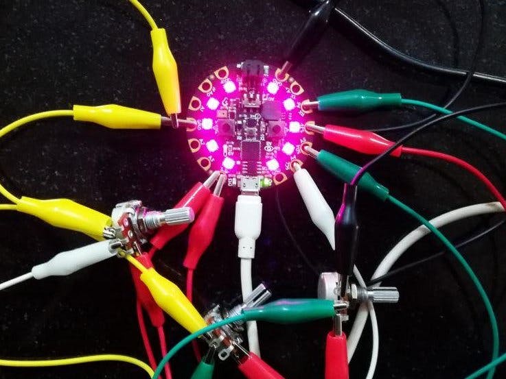
Color tint in macro photography look pretty awesome, right? Adafruit's CircuitPlayground board has 10 RGB NeoPixels that can be used for designing this ambient tint ¯\_(ツ)_/¯. We'll go through 2 ways to make this thing:
- Using potentiometer in-order to control intensity of colors
- Using just the on-board buttons to control the intensity of colors
It's actually a little messy because of all these alligator clips! But all effort count, so let's start by writing a simple analogue input code. Wire the potentiometer like the diagram below:
CircuitPython provides with core module called analogio which handles all the analog input output operations. Look at the example code below:
import board
import analogio

analogin = analogio.AnalogIn(board.A1)

def getVoltage(pin): # helper
    return (pin.value * 3.3) / 65536

while True:
    print("Analog Voltage: %f" % getVoltage(analogin))
It'll work like a charm but the input in between 0.0 - 3.3. And, now there's a problem that neopixles requires a input in-between 0 - 255. If it were a Arduino, instead of Express board then it'd be a matter of seconds to tackle this problem by putting a map function but here you'll have to implement a similar map function. Thanks to scruss for this answer which does the work just as we want it to be.
My pin assignments and map function looks like this:
red = analogio.AnalogIn(board.A6)
blue = analogio.AnalogIn(board.A5)
green = analogio.AnalogIn(board.A4)

def valmap(value, istart, istop, ostart, ostop):
    ret = round(ostart + (ostop - ostart) * ((value - istart) / (istop - istart)))
    return 0 if ret < 4 else ret
and my main loop looks like this:
while True:
    red_ = valmap(getVoltage(red), 0.0, 3.3, 0, 255.0)
    blue_ = valmap(getVoltage(blue), 0.0, 3.3, 0, 255.0)
    green_ = valmap(getVoltage(green), 0.0, 3.3, 0, 255.0)

    cpx.pixels.fill((red_,green_,blue_))
Final code lives here -> https://github.com/nk521/cktpy/blob/master/macro_photography_rgb.py
The on-board wayThe express board provides with two push button and one slide switch which I used in this code.
- Switch A will always increase the intensity/brightness
- Switch B will always decrease the intensity/brightness
I made two modes which will be accessible by slide switch.
- One mode will be the color mode in which you can change the color
- Other mode is the brightness mode in which you can increase/decrease the brightness using two push buttons.
Now I don't have any I/O which I can use to switch between the colors (R, G and B) so I made the switching between the colors possible my pressing both the push buttons at once. On-Board LED (D13) will let you know in which mode you're in ->
- If you see the D13 light then you're in RED mode and push buttons will increase/decrease the amount of RED you want.
- Now if you press both buttons at once then you'll notice D13 is blinking which means you're in GREEN mode.
- Pressing both once again will throw you in BLUE mode and in this case D13 will be off.
Sliding the switch will put you either in color mode or brightness mode. Here's how everything works:
Summary- Button A will always increase the value (let it be brightness or intensity).
- Button B will always decrease the value.
- D13 LED will indicate on which color (R, G or B) you are. Glowing D13 indicates Red color, Blinking D13 indicates Green color and if D13 is not glowing at all then you're on Blue color.
- Slide switch will either put you in color change mode or brightness change mode.
Signing off with a not-so-good picture of a Raspberry Pi 3 with CircuitPlayground board in background lighting it up!


Comments
Please log in or sign up to comment.