You may want to review Upload AVR Assembly program to Arduino Uno with MicroChip Studio. In that project we install MicroChip Studio and programmed a Uno.
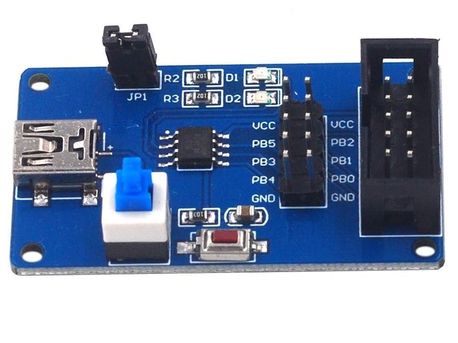
ATtiny13 DevBoardThere are a few variations for LEDs and buttons but the ATtiny13 is just an Arduino that only has PORTB. That can be enough for many applications. We'll use a USBasp type external programmer.
The vendor provides this image of the board. LED D1 is connected to pin B3 and D2 is connected to pin B4. The blue button is for USB power and the red button resets the board.
Open a New Project in MicroChip Studio either with the menu File->New->Project or Ctrl+Shift+N on the keyboard. Choose assembler project and name it at13.
Select ATtiny13 as device.
MicroChip Studio will generate a default main.asm file with placeholder code. Build the project menu Build->Build Solution or press F7 on your keyboard. We are looking for a Build succeeded message that tells us our setup (toolchain) is okay.
Replace the default code with this program. It will generate a binary count on PORTB. Delays are generated by making the program run through an outer loop and inner loop. Change the number of loops and you change the delay.
.include "tn13def.inc"
    .def	mask 	= r16	; mask register
    .def	ledR 	= r17	; led register
    .def	oLoopR 	= r18	; outer loop register
    .def	iLoopRl = r24	; inner loop register low
    .def	iLoopRh = r25	; inner loop register high
    .equ	oVal 	= 80	; outer loop value
    .equ	iVal 	= 2000	; inner loop value
    .cseg
    .org	0x00
    clr	    ledR		; clear led register to zero
    ldi	    mask,0xFF		; load the mask register 11111111
    out	    DDRB,mask		; set PORTB to all 8 bits OUT
start:
    out	    PORTB,ledR		; write led register to PORTB
    inc     ledR		; increment ledR from 0 to 255
    ldi     oLoopR,oVal		; initialize outer loop count
oLoop:
     ldi    iLoopRl,LOW(iVal)	; intialize inner loop count in inner
     ldi    iLoopRh,HIGH(iVal)	; loop high and low registers
iLoop:
    sbiw    iLoopRl,1	        ; decrement inner loop register
    brne    iLoop		; branch to iLoop if iLoop register != 0
    dec	    oLoopR		; decrement outer loop register
    brne    oLoop		; branch to oLoop if outer loop register != 0
    rjmp    start		; jump back to start
Build the project menu Build->Build Solution or press F7 on your keyboard. The Build succeeded message that tells us our program has generated a hex file that we can upload to an ATtiny13 processor.
We are going to setup a programmer device to upload our firmware. Menu Tools>External Tools...
Click Add to add a new tool, give it the title tiny13
Command:avrdude.exe the computer has to have avrdude software. This program was installed with MicroChip Studio.
Arguments:
-p t13 -c usbasp -U flash:w:$(BinDir)\$(TargetName).hex:iThese options are for avrdude to upload a flash program to an ATtiny13 using an external USBasp device. USBasp and USBtiny programmers not have a com port number.
The hex file to upload to the device flash memory is in a debug folder named at13 inside of a project folder named at13. To automatically find the file this scripted text is added -U flash:w:$(BinDir)\$(TargetName).hex:i.
Upload Flash ProgramGo to the menu Tools->Tiny13 and there should be a quick blink on your computer screen. A black window opens and closes because the upload happens so fast.
The ATtiny development board should have LEDs blinking on its PORTB connections. Remember your LED should have a resistor and connect to ground.


Comments