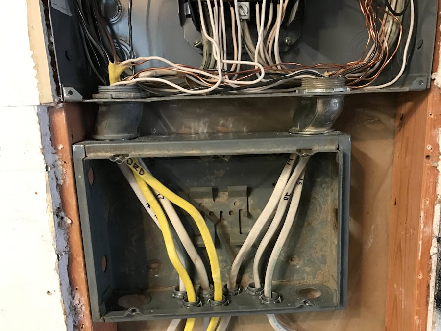
The idea of this project is to monitor each channel in my circuit breaker panel for current draw by attaching a current clamp around each line going into the house. It will display on an LCD panel in the kitchen for real time readings.
SafetyA friend of mine is a home inspector and his advice is to put the sensors in electrical boxes outside of the main breaker box. Since the wires going into my main box enter from the top and bottom, I'll install two.
Using a current clamp keeps the electronics isolated from the main power system. Anyone using the display panel inside will be sufficiently isolated from dangerous voltages.
MeasurementThe current clamps will connect to a series of filter circuit and then to the PSOC Analog Coprocessor board. The PSOC board will calculate the R.M.S. value of the voltage input and report the values over I2C to an Arduino for display.
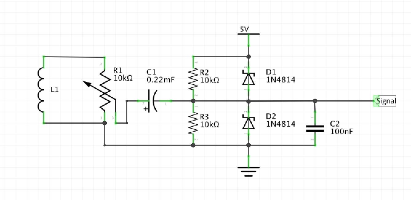
Filter CircuitThe first part of the filter circuit is a trim pot. This will allow calibration. The output from there is coupled by a capacitor to the center of a voltage divider. The signal will cause variations on the 2.5V reference voltage. High frequency noise is reduced by a small capacitor. A pair of diodes offer over voltage protection.
Please read the project logs to see how this all unfolds.


_ztBMuBhMHo.jpg?auto=compress%2Cformat&w=48&h=48&fit=fill&bg=ffffff)


Comments
Please log in or sign up to comment.