In this project, we designed a line-following car using an Arduino and IR sensors. This project is perfect for beginners and enthusiasts interested in robotics and automation. Line-following robots are commonly used in industrial applications for automated guided vehicles (AGVs)..
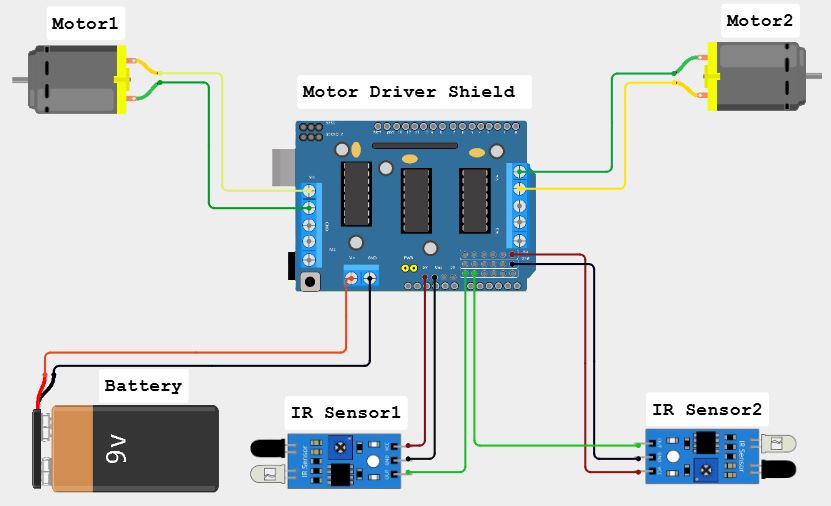
Wiring Diagram Explanation1.MotorsLeft Motor:
- Connect one wire to the M1 terminal on the motor driver shield.
- Connect the other wire to the other M1 terminal on the motor driver shield.
Right Motor:
- Connect one wire to the M4 terminal on the motor driver shield.
- Connect the other wire to the other M4 terminal on the motor driver shield.
2.IR SensorsLeft IR Sensor:
- Connect the VCC pin to the 5V pin on the motor driver shield.
- Connect the GND pin to the GND pin on the motor driver shield.
- Connect the OUT pin to the A0 pin on the motor driver shield.
Right IR Sensor:
- Connect the VCC pin to the 5V pin on the motor driver shield.
- Connect the GND pin to the GND on the motor driver shield.
- Connect the OUT pin to the A1 pin on the motor driver shield.
3.Power Supply:Connect the battery pack to the power input terminals on the motor driver shield.
4.Motor Driver Shield:Plug the L293D motor driver shield directly onto the Arduino Uno.
Demonstration


_ztBMuBhMHo.jpg?auto=compress%2Cformat&w=48&h=48&fit=fill&bg=ffffff)


Comments
Please log in or sign up to comment.