My goal for this project was to build a motorized opener for my mini-blinds that I could control with an Android app. There is a funded Kickstarter for a blinds opener but I decided to just make my own for fun. A secondary impetus for this project was to learn more about electronics hardware and software development. I also had been wanting to use the ESP8266 WiFi integrated micro-controller in a project.
I completed this project in 2017.
The blinds I am used for this project are typical horizontal mini-blinds with the wand on one side to tilt the blinds and the chords on the other side to pull the blinds up. This project only deals with tilting of the blinds.
Project Requirements- Open and close blinds with Android app.
- Must be able to open blinds without the app as well.
- Low energy use. Motor must be enabled only when actively used.
- Intuitive controls.
- Must be reliable and safe.
- Powered from a DC Power supply. No batteries.
- No irreversible modification of blinds.
In the upper housing of the blinds is a steel hex shaped rod that runs the length of the blinds. Turning this rod changes the angle of the blades. I had a stepper motor that fit inside this upper housing and aligned almost exactly with the hex shaped rod. I was able to connect the stepper motor to the rod with a shaft coupler.
There is a gearbox that only allows this rod to be rotated by the twisting the wooden wand. I had to remove this gearbox so that the rod could be turned by the stepper motor. I also had to devise a way to hold the rod's position when the motor is not powered. Without something to maintain the rods position the blind's blades would tilt down.
The solution was to hold the rod with enough friction so the rod would not move unless the motor spins with enough torque to overcome this holding friction. This was accomplished by taking a block of wood with a hole for the hex rod and a threaded hole perpendicular to the rod for a set screw. At the end of the set screw is a piece of rubber and when the set screw is tightened the rubber plug is pressed against the rod. Through trial and error the machine screw was adjusted to the rod was held firmly but not so firm that the motor would struggle to turn it.
The block and motor are held in place with rubber shims. The modifications to the blinds were inexpensive and did not require irreversibly modifying the housing. The gearbox was easily removed and could be put back with no issue.
The stepper motor alters the blind's tilt angle. I decided to use a gyro/accelerometer sensor to measure the angle of the blades; providing feedback to the stepper motor. I suppose I could have just tracked the steps taken by the stepper motor to determine position but I thought directly sensing the angle would be more reliable. The sensor was simply attached to one of the upper blades with double-sided tape.
I decided to use a stepper motor over a servo motor because standard servos do not have enough angle travel without a gearbox. I also find stepper motors easier to work with since they do not require precise timing. I could have used a DC motor with an encoder but that seems overly complicated for the task.
I used the Pololu A4988 Stepper Motor Driver and the Adafruit BNO055 Absolute Orientation Sensor. The BNO055 was kind of expensive. I am sure a cheaper sensor could be found. It just might require more work interpreting the data.
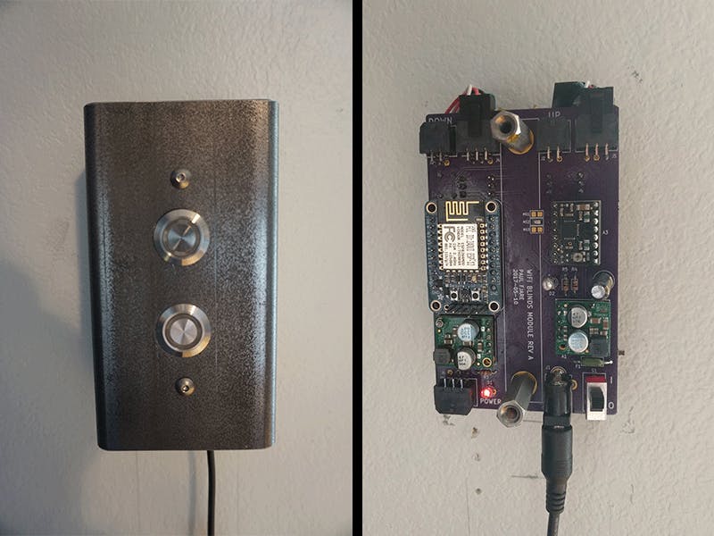
Electronics HousingOn the wall next to the window is a housing that contains the two interface buttons and the electronics. The stepper motor and orientation sensor plug into this housing. The project is powered by a 12V, 3A switching DC power supply that plugs into the bottom of the housing.
The housing was cut from a 3" x 3" steel box beam section. I was concerned about the steel blocking the WiFi signal but I haven't noticed any problems.
The wires for the motor and orientation sensor are hidden in the wall. I used shielded cable to minimize the effects of EMI. During prototyping, EMI from the stepper motor wires caused the orientation sensor to malfunction.
The PCB was designed in KiCad. All the PCB components are though-hole components for ease of soldering. It was printed by Osh Park https://oshpark.com/. They did a great job.
Main components
- Adafruit HUZZAH ESP8266 Breakout
- Pololu A4988 Stepper Motor Driver Carrier
- 5V step-down voltage regulator
- 3.3V step-down voltage regulator
- Neopixel LEDs (on back)
I also created a small Debug Module that plugs into the main board that allows me to put the ESP8266 into bootloader mode and access the serial lines without taking the housing off.
The gerber files and schematics for both boards are available here https://gitlab.com/pfjare/wifi-blinds-pcb.
The BOMs are available here https://docs.google.com/spreadsheets/d/1uPH0UYzaFl-pABCBGOthaaIexG82jPdf_6R0eSZoJQ4/edit?usp=sharing
ESP8266 Codehttps://gitlab.com/pfjare/wifi-blinds-ESP8266/blob/master/blinds/blinds.ino
The code that runs on the ESP8266 is fairly simple. I take steps to make sure that the orientation sensor is fully operational before the stepper motor is allowed to move. I use the following libraries in the code:
- Adafruit_BNO055: I had to make a few small modifications to this library. You can find my custom version here.
- Adafruit_Sensor
- arduinoWebSockets
- Adafruit_NeoPixel
The app makes a websocket connection with the ESP8266 and disconnects when the app is not showing. When a button is pressed a message containing the desired blinds angle is sent to the ESP8266. There are four buttons Closed Up, Full Open, Part Open, and Closed Down.
I used the nv-websocket-client WebSocket library.
The source code for the app can be found here https://gitlab.com/pfjare/wifi-blinds-android.


Comments
Please log in or sign up to comment.