

Hardware components | ||||||
 |
| × | 1 | |||
| × | 1 | ||||
| × | 1 | ||||
| × | 1 | ||||
| × | 1 | ||||
| × | 1 | ||||
Software apps and online services | ||||||
 |
| |||||
 |
| |||||
| ||||||
| ||||||
| ||||||
Hand tools and fabrication machines | ||||||
 |
| |||||
Off the bat let me say that Arduino continues to be the standard setter for technology & quality, but, most impressively, for world-class customer support. Sure, you'll pay a bit more, but you'll get it back. With gains.
This latest contraption of mine follows the need to assist some people in falling and staying asleep and then, smoothly waking up. (If you're a parent, you´ll be the one receiving the assistance...ha ha).
It's a working prototype, so it works, but it's a prototype, which means there are still wrinkles and speed bumps. In any case, this is a fully documented tutorial of the What's, the How's and the Why's, with many tips 'n tricks and lots of comments embedded in the Arduino code.
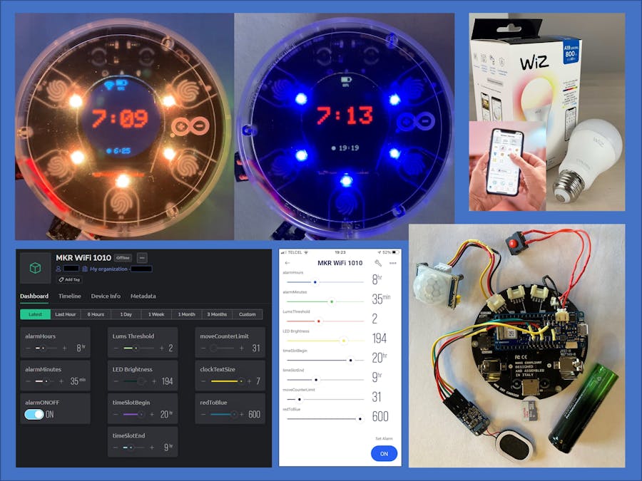
FUNCTIONAL DESCRIPTIONNIGHT LIGHT. Using a decision matrix based on the state of 4 variables (time of night, amount of movement detected, amount of light detected & calm time elapsed), the various system resources are activated: On-Board LEDs & clock TFT display color, playback of white noise intervals, playback of recorded messages, setting of the room's lighting color & intensity or turn it off (Philips WiZ light bulbs).
WAKE UP ALARM. The wake up sequence begins 30 minutes prior to the defined alarm time with a gradual power up of the Philips WiZ light bulbs, from low intensity warm colors to full brightness white light (a daybreak simulation). The on-board LEDs begin 10 minutes prior with a blue color sequence, from lowest to highest brightness. During the last 10 minutes, selected short tunes are played (i.e. Super Mario, etc.). Finally, at alarm time, a recorded message is played (i.e. "It's time to wake up!").
SYSTEM PARAMETERS. Some variables, including of course the Alarm Time, but also the LED brightness for night light service, the time slot to be considered as sleeping time, the amount of light to be considered dark, the number of movements detected within a time period, and other variables, can be set via Web or Phone using Blynk. To save battery, shaking (or just grabbing) the Opla will turn the WiFi radio off. When connecting to IFTTT (to control the WiZ lights), WiFi is turned on/off as required.
LEDs & Clock display colors. The colors were selected based on some studies showing how different colors of light could affect our ability to sleep. (Lighting color affects sleep, wakefulness - Oxford's Sleep and Circadian Neuroscience Institute)
Use of White Noise. There are mixed results in the use of white noise for sleep. Some noise "colors" may be better than others. The most common is "White". Some recommend "Pink". I'm using "brown" noise for this application (also known as "Red" and also used to stimulate concentration). A good source for test tones ("colored noise") is Audiocheck.
Playback of WAV Files. The speaker & Mono Amp are connected to (the only available) DAC, which is also used as A0 in the touch sensors, which created a click sound with every program loop. I disabled A0 in my local copy of the MKR IoT Carrier library programs (I'm not using the touch sensors, and in any case that still leaves the other 4 touch sensors) but then discovered that clock management of the SamdAudioSD library (to handle 8-bit mono PCM WAV in SAMD-based boards) created conflicts with other MKR IoT Carrier functions, so I had no choice but to block execution during playback and use the amplifier's Shutdown pin tied to digital pin 14 of the MKR1010 board (I'm not using the carrier's relay assigned to D14) to turn it on/off.
The pre-recorded messages are easily produced, enhanced and converted to 8bit mono 44.1Khz PCM WAV format using Audacity, an amazing open source audio editor & recorder. You can also add all sorts of sounds and special effects from Freesound. The WAV files with the recorded messages and the brown noise samples are stored in the Micro SD Card.
(Note: I commented out all references to the digital Pot functions in my local copy of SamdAudioSD.cpp since I'm not using a digital potentiometer and those sections created compile errors).
Control of Philips Wiz Light Bulbs. Using IFTTT Webhook integrations and IFTTT WiZ Integrations, I created 3 applets. All are called using specific GET HTTP requests (make sure to use a secure https connection). One applet starts the wake up sequence in the WiZ App, another is called to turn on the WiZ bulbs at very low levels and the third is used to turn the WiZ bulbs off.
Free accounts in IFTTT allow for up to 5 applets. After you create an account, you can access your key & JSON details. Visit their Connect API documentation for complete details.
Playback of Tunes in the Piezo Buzzer. The on-board piezo buzzer can be used for simple tunes. I used Dipto Pratyaksa's code for playing Mario Bros tunes that is based on the pitches defined in the Tone Tutorial from Arduino. You can find a long list of songs in Robson Couto´s github library of Arduino Songs for the piezo buzzer.
Solving for Hysteresis in Light Intensity Readings. The APDS9960 provides analog readings from 0 to 4096, allowing for a wide range of luminance analysis. To analyze the room luminance for sleep, only very low readings, below 20 or 30, are relevant (0 being total darkness), so an effect called hysteresis comes into play. Anonymous user 6v6gt created a wonderful tutorial in the Arduino Forum that includes software implementation and group discussion. I made some mods to his code to allow for non linear margins (see my comments in code).
Caution when Using a PIR Sensor. There are some nuances when using a PIR sensor regarding sensitivity and blocking time that should be considered. Adafruit has a good guide on the subject. In my code, I consider some elements to avoid "false positives", like moving in bed but not really awake.
CODING CONSIDERATIONSDecision Matrix. The actions to execute depending on the status (true/false) of each of the four variables defines 16 possible states (a 4 bit variable is used to manage states). States 9, 11, 13 and 15 are not evaluated for they can't occur (i.e. It's been calm for the last x minutes and True positive movement has just been detected).
Non Blocking Code. As already mentioned, blocking execution during playback of WAV files was unavoidable. Other than that, I only use delay() statements when starting services (i.e. WiFi, Blynk, Serial). Throughout the program you'll find several timers based on millis() to avoid any blocking code.
Battery Monitoring. The program checks the battery level every 5 seconds (faster than this and hysteresis kicks in, making the displayed value jump up and down) then maps the max reading of 1023 (analog pin) to the 25 pixels of the screen icon. I'm not sure if it's the MKR1010 or the 16850 battery I found that cuts power at 3.1v (brownout), but in any case, the min reading for the display is mapped to 73% of max.
Time of Day. The system acquires the time of day from Blynk at startup, using ISO-8601 format to allow for time zones, and then updates the MKR1010's real time clock (RTC).
Color Management in the MKR IoT CarrierResources. When defining colors in code for repeated use, consider that the on-board LED strip of the MKR IoT Carrier uses 32-bit color with Adafruit's DotStar library. Also note that the LED strip is GRB, nor RGB, relevant when using methods like carrier.leds.color(G, R, B) to create the 32-bit value. To pick 32-bit colors, I used w3scools' HTML Color Picker. The TFT display uses 16-bit colors with Adafruit's ST-7735 library. To pick 16-bit colors, I used Chris Hewitt's RGB565 Color Picker.
FINAL ASSEMBLYThe Mono AMP is connected to the MKR1010 via right angle headers. This permits the connections and wires to lie between the stacking headers of the board to close the lid on the Opla's case.
The On/Off Switch was added in the Vcc cable run between the MKR IoT Carrier and the MKR1010 board to provide such function when running on battery. Without this, either you use it until your run out of battery, or you take out the back cover to pull the battery out. Certainly an area for improvement for the Opla IoT Kit.
The PIR sensor was fitted with shorter cables to lie closer to the case when assembled. The On/Off switch also lies outside the case. The remaining elements fit inside with the case's back lid solidly in place.
I'll be field testing this thing with my son over the next few weekends and report back on its effectiveness as well as changes (and corrections) to be made.
If you made it this far into the story, it probably means you have an opinion, so leave a comment and add to this wonderful community Arduino has built for us.
_FISDBZmhgB.bmp)


_FISDBZmhgB.bmp)
Comments