


Hardware components | ||||||
| × | 1 | ||||
| × | 1 | ||||
| × | 1 | ||||
| × | 1 | ||||
| × | 1 | ||||
| × | 1 | ||||
| × | 1 | ||||
| × | 1 | ||||
| × | 4 | ||||
Software apps and online services | ||||||
 |
| |||||
 |
| |||||
In an upcoming project I needed a way to detect when the power in my house went off and I needed to detect when the pump was running. There are sensors that can be purchased but I thought it would be fun to build one.
In an effort to keep the other project from becoming over-complicated I decided to share the details of building this simple device in a separate project.
Device OverviewThe device I am building is rather simple and requires only a few inexpensive components. The most expensive component is the 105-125VAC pilot light (the cost of which is about $7.00). A pilot light is a light that is commonly used as a power indicator on an appliance in your home.
The concept of the device is to use a photoresistor to detect light from the pilot light. Using a simple voltage divider circuit and the 3.3v source from the Raspberry Pi, the device will output a high signal when the voltage across the input terminals is 0 and a low signal when the voltage across the terminals is 120VAC.
A big advantage of this design, other than the low cost, is that the AC circuit is completely isolated from your IoT device. This protects your Raspberry Pi and other circuit components from a power surge.
Device OperationThe circuit design is based on a voltage divider circuit which consists of two resistors in series between the power source and ground (or any higher and lower voltage potential). The voltage is measure from the point between the two resistors and the lower of the two voltage potential points (ground in this case). Usually, in a voltage divider circuit, both resistors are fixed. In this circuit one of the resistors changes its value when the intensity of the light changes allowing the device to alter the output voltage based on the light source.
This device is intended as a two state device, meaning, I only want to detect if the AC input circuit is on or off. The output of the circuit needs to be detected by the GPIO pin as high or low. To accomplish this the value for the fixed resistor must be chosen carefully.
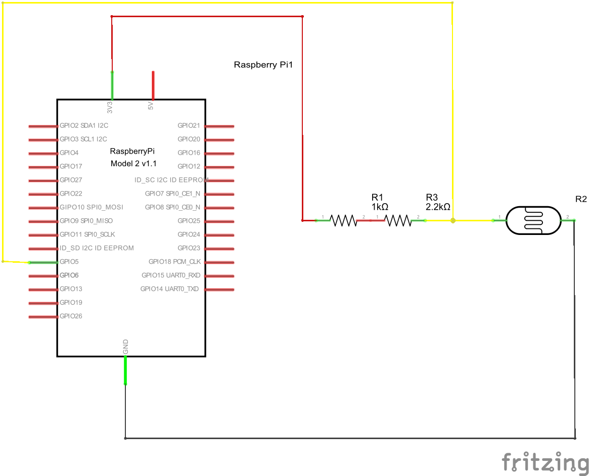
The key to the circuit is to determine the right resistor for R1 in the above diagram. The resistance of photoresistor varies by the amount of light. When it is completely dark, the resistance is 90K to 100K Ω. With a fully bright light source it drops to about 200 Ω.
Calculating the correct resistor value for R1 depends on the amount of light available. The light source may not be bright enough to drop the resistance to the lowest measured value. With this in mind I measured the resistance value using the amber pilot light. I performed this measurement by placing the light source inside a black heat shrink tube with the photoresistor press against the light and then measured the resistance with a volt/ohm meter while the light was on. The black tube is necessary in order to simulate the conditions I would have when the device is fully constructed
The tube was not heated for this measurement
The experiment yielded a measurement of 941 Ω. Using the standard formula for the voltage divider (shown in the images below) and targeting low voltage of .75v I determined that the value for R1 needrf to be 3.2K Ω.
In the circuit design, to get 3.2K Ω I decided to use a standard 1K Ω and standard a 2.2K Ω resistor in series (both the 1K Ω and the 2.2K Ω are standard sizes that you will most likely have in your toolbox).
Load Effect When a device such as Raspberry Pi is connected between Vout and ground the device is referred to as the load This load has an effective input impedance that alters the behavior of the circuit which may warrant a design change to counter the effect. To help understand this effect think of the load as a new resistor added across the Vout and ground on the circuit diagram. In this device, when used with the Raspberry Pi, the load effect can be ignored because the output current is stable and it is a small percentage of the divider's input current. For this reason I was able to design this as a passive circuit to keep cost low. Devices that perform this function could cost significantly more if they contain regulator circuits to allow for varying loads on the output.
Building this device requires a soldering iron and a good place to solder the components together. There is no PCB board used, I simply connect the pieces together and then shrink wrap them for protection. Make sure you have a good surface to lay the components on.
- Trim both ends of the two resistors and the photoresistor leads to about 1.5 cm
- The resistors will be soldered in series to one of the photoresistor leads (see the images below) overlapping the leads by at least 1 cm. Lay out the photoresistor and the first resistor.
- Start by soldering the first resistor to the photoresistor lead. Press the iron against the leads and then solder the two leads together making sure to have solder run the length of the overlapping pieces
- Lay out the second resistor in the same manner as the first
- Next solder the second resistor to the first resistor in the same manner (the order of the two resistors does not matter)
- Strip about 1 cm from the end of the Red lead and solder it to the end of the second resistor. This lead will connect to the 3.3v source on the Raspberry Pi
- Strip about 1 cm from the end of the Yellow lead and solder it the lead on the photoresistor that the first resistor is connector to. This lead will connect to the GPIO port on the Raspberry Pi
- Strip about 1 cm from the end of the Black lead and solder it to the end of the second resistor. This lead will connect to ground on the Raspberry Pi
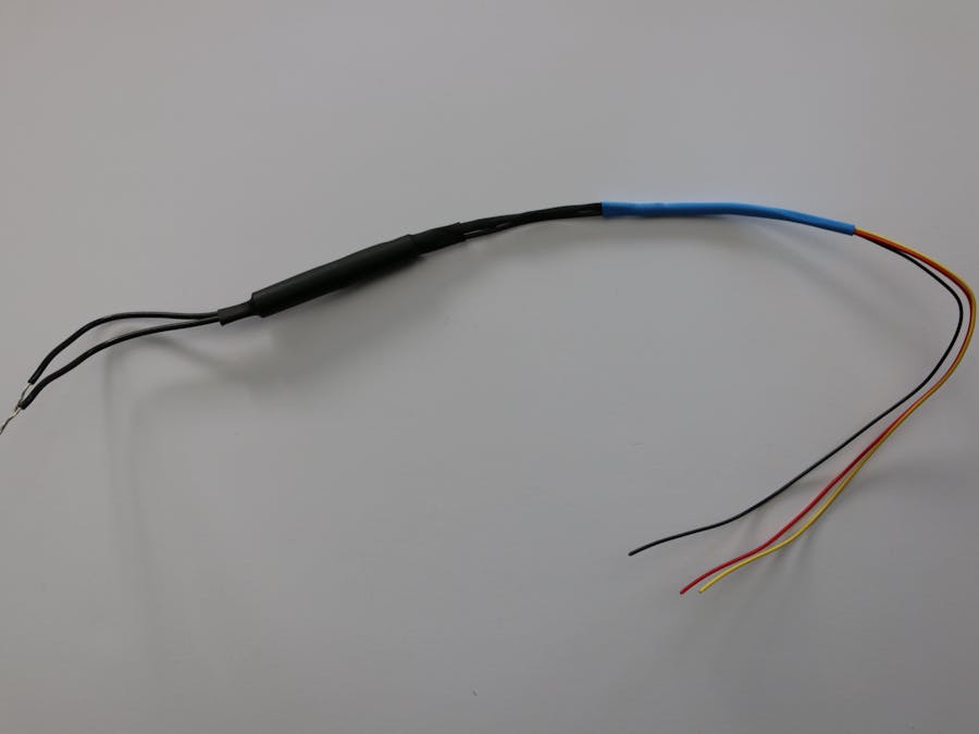
- Slip the 3/32" heat shrink tube over the black wire all the way to the photoresistor as push it up against the resistor. Heat the tube so it locks in place (I used black for this strip)
- Slip the 3/16" heat shrink tube over the red and yellow wires all the way to the photoresistor as push it up against the resistor. Heat the tube so it locks in place (I used black for this strip)
- Slip the 1/4" heat shrink tube over all three wires and overlap the end of the other tubes by about .5 cm. Heat the tube so it locks in place (I used blue for this strip)
- Slide the pilot light into the hard plastic tube so that the end with the wires is just even with the end of the tube
- Slide the photo resistor assembly into the other end of the hard plastic tube until it is up against the pilot light
- Slip the 3/8" heat shrink tube over the hard plastic tube until it is centered over the tube. Approximately 3/4" should hang over each end. Heat the tube until it is locked in place (it may be necessary to hold the photoresistor assembly in place with one hand while you heat the tube). NOTE: the tube color in the previous steps does not matter but I recommend black for this step to ensure no light escapes from the device
- Trim the red, black and yellow wires so they are all even
Why a mix of metric and imperial units? Throughout the tutorial I mix the use of metric and imperial units intentionally. I am using imperial units for larger sizes. In addition, when I purchase materials and they are expressed in imperial units I specify the sizes in these units. When dealing with smaller sizes I usually express them in metric. I hope this does not cause too much confusion for some people.
Now that the device is completed it is time to run a test. I first located a cord I had previously cut from a failed portable air conditioning unit (I saved the cord because it has a built it circuit breaker). Any old two wire extension cord will work. The white and black wires from the extension cord should be connected to the wires of the pilot light using wire nuts. My cord has a third green ground wire which I just covered up with another wire nut. Make sure the connections are tight and do not come loose when moving the device around. Also make sure there are NO bare wires from the cord exposed.
DISCLAIMER: Working with high voltage AC current can be very dangerous if you do not know what you are doing. If you are uncomfortable or unsure about how to do this please consult with an expert. You are attempting these tests at your own risk!
After connecting the extension cord I plugged the cord into a power strip with an on and off switch to make it easy to test the operation of the device.
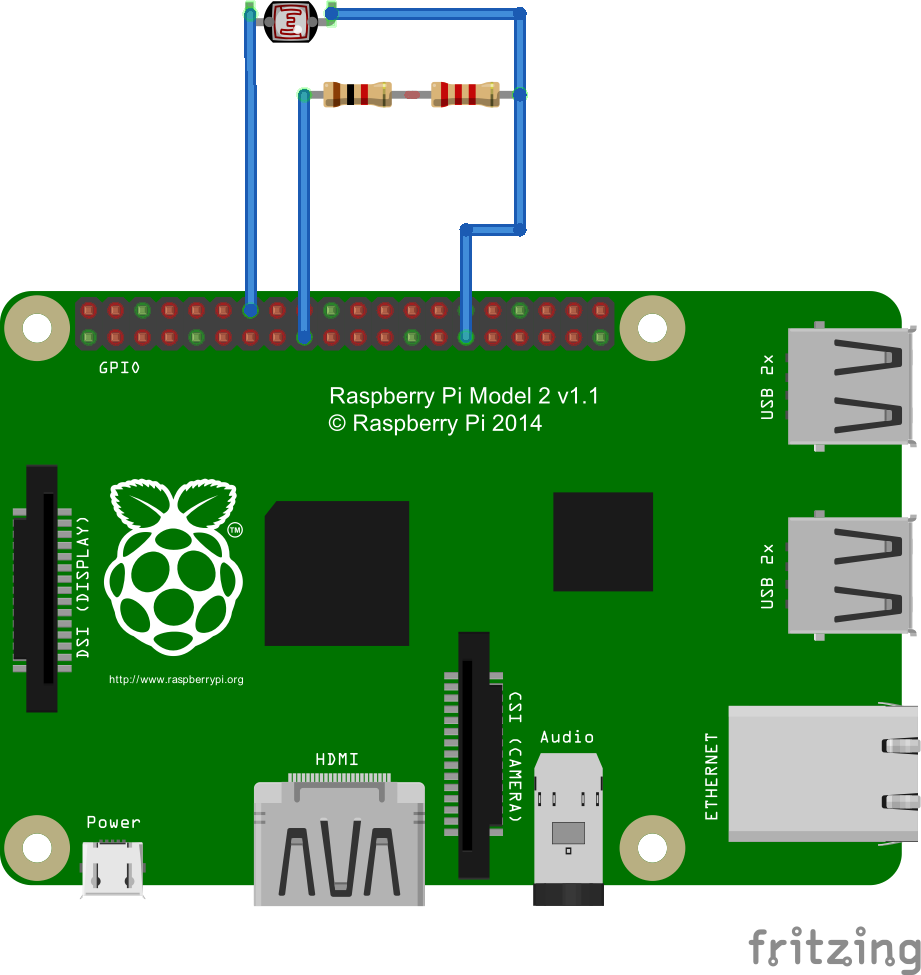
Next I connected the red wire from the device to the Raspberry Pi's +3.3V pin, connected the black wire to the Ground pin and connected the yellow wire to one of the GPIO ports on the Pi (I use GPIO 5 in the source code).
Running the SoftwareThe source code used is available in GitHub (see the link below).
The application is a simple view that shows the status of the GPIO pin as "High" or "Low". When connected turning the power strip off will result in the display showing "High". Turn the power on the status will change to "Low".
The XAMl for the main form is shown below.
<Page x:Class="VacSensor.MainPage"
      xmlns=
      xmlns:x="http://schemas.microsoft.com/winfx/2006/xaml"
      xmlns:local="using:VacSensor"
      xmlns:d="http://schemas.microsoft.com/expression/blend/2008"
      xmlns:mc="http://schemas.openxmlformats.org/markup-compatibility/2006"
      mc:Ignorable="d"
      RequestedTheme="Dark">
    <Grid Background="{ThemeResource ApplicationPageBackgroundThemeBrush}">
        <TextBlock Text="{x:Bind GpioState, Mode=OneWay}"
                   HorizontalAlignment="Center"
                  VerticalAlignment="Center"
                   FontSize="180" />
    </Grid>
</Page>
The code behind for the main view is shown below.
using System;
using System.ComponentModel;
using System.Runtime.CompilerServices;
using System.Threading.Tasks;
using Windows.Devices.Gpio;
using Windows.UI.Core;
using Windows.UI.Xaml.Controls;
using Windows.UI.Xaml.Navigation;
namespace VacSensor
{
	public sealed partial class MainPage : Page, INotifyPropertyChanged
	{
		private GpioPin _pin = null;
		private CoreDispatcher _dispatcher = null;
		public MainPage()
		{
			this.InitializeComponent();
		}
		public event PropertyChangedEventHandler PropertyChanged = null;
		private void OnPropertyChanged([CallerMemberName]string propertyName = null)
		{
			if (this.PropertyChanged != null)
			{
				this.PropertyChanged(this, new PropertyChangedEventArgs(propertyName));
			}
		}
		private string _gpioState = "Unknown";
		public string GpioState
		{
			get
			{
				return _gpioState;
			}
			set
			{
				this._gpioState = value;
				this.OnPropertyChanged();
			}
		}
		private async Task UpdateUI()
		{
			if (_dispatcher != null)
			{
				await _dispatcher.RunAsync(CoreDispatcherPriority.Normal, () =>
				{
					GpioPinValue value = _pin.Read();
					this.GpioState = value == GpioPinValue.High ? "High" : "Low";
				});
			}
		}
		protected async override void OnNavigatedTo(NavigationEventArgs e)
		{
			_dispatcher = CoreWindow.GetForCurrentThread().Dispatcher;
			GpioController gpio = GpioController.GetDefault();
			if (gpio != null)
			{
				_pin = gpio.OpenPin(5);
				_pin.SetDriveMode(GpioPinDriveMode.Input);
				_pin.ValueChanged += Pin_ValueChanged;
			}
			await UpdateUI();
			base.OnNavigatedTo(e);
		}
		protected override void OnNavigatingFrom(NavigatingCancelEventArgs e)
		{
			if (_pin != null)
			{
				_pin.Dispose();
				_pin = null;
			}
			_dispatcher = null;
			base.OnNavigatingFrom(e);
		}
		private async void Pin_ValueChanged(GpioPin sender, GpioPinValueChangedEventArgs args)
		{
			await UpdateUI();
		}
	}
}
To test the unit deploy the code to the Raspberry Pi and start it using F5. Once the application is running, switch the power on and off on the power strip and the display will change each time.
This device can also be used with a 5V logic device such as the Arduino.
For 3.3V logic a voltage greater than 2V is consider high while a voltage less than 2V is consider low. Subsequently on 5V logic a voltage greater than 3V is consider high while a voltage less than 3V is considered low.
When I connected the device to the 3.3V source on the Raspberry Pi the high output voltage measured at 3.300V on a Fluke 87 meter. The low output voltage measured at .752V.
When I connected the device to the 5V source on the Raspberry Pi the high output voltage measured at 5.140V. The low output voltage measured at 1.160V.
Both well within the desired range for either a 3.3V or 5V logic circuit.
CalibrationI gave some thought to adding a trimmer (a pot type potentiometer) to allow for calibration of the device. I didn't try it mainly for the reason that I didn't have one. Depending on the type of light source, it may be easier to build the circuit with one of these and then calibrate the device after it has been built. The size (ohm range) of the pot should be carefully chosen to fall within the range needed to get the correct voltage.


Comments