


Hardware components | ||||||
| × | 1 | ||||
 |
| × | 1 | |||
 |
| × | 1 | |||
| × | 1 | ||||
 |
| × | 1 | |||
 |
| × | 1 | |||
| × | 1 | ||||
| × | 1 | ||||
 |
| × | 1 | |||
Software apps and online services | ||||||
 |
| |||||
| ||||||
In this project, I want to demonstrate how a regular fridge can be turned "smart" by attaching a Particle Photon microcontroller, sensors, and actuators to it, in order to collect passive data about it (e.g. temperature) as well as event-driven data (e.g. door opened/closed).
As an additional requirement, I want to make the Photon as energy efficient as possible, by turning off its Wi-Fi adapter when the room in which the fridge is located has been empty for some time, and turning it back on when somebody is detected in the room.
SensorsReed Switch
Arguably the most important data to get from a smart fridge is for it to tell you whether anybody is using it. A reed switch can help to find this information. It is an electrical switch that changes its state when a magnetic field is applied to it (i.e. a magnet). Luckily, the door of my fridge is lined with a magnet.
My reed switches are normally open (N/O) i.e. normally switched off. When a magnet is applied to the switch, it closes the circuit. The image below illustrates how this works.
Conversely, there are normally closed (N/C) reed switches, that work in reverse fashion. These can work for this project also, but would require slight alteration to the code presented later on.
Temperature Sensor
Also important is the current temperature of the fridge. I will use a temperature sensor for this and fit it inside the fridge as far from the door as possible. This is to get a more representative temperature readings, as the door opening and closing would lead to larger and less accurate temperature changes if the sensor were closer to the outside world.
Buzzer
In order to maintain a low temperature, it's important that nobody leaves the fridge door open for too long! I will use a buzzer that activates when the fridge door has been left open for approximately 25 seconds.
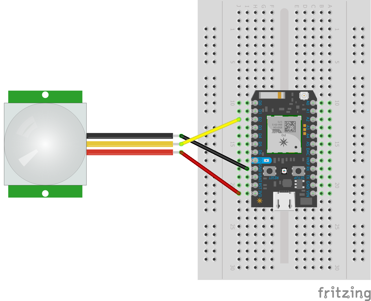
PIR Sensor
For energy efficiency, I will use a PIR sensor to detect motion in the room to determine whether anybody is present. If nobody is detected for approximately 3 minutes, the Photon enters a low-power mode that turns its Wi-Fi adapter off, and sends data at much larger intervals, i.e. from every 5 seconds to every 5 minutes.
Sending data this sparsely is fine because, if nobody is in the room to interact with the fridge, then the data shouldn't change much: the reed switch will remain in its "door closed" state, the PIR will remain in its "no motion detected" state, and the temperature should stay consistent.
When somebody enters the room, the PIR sensor will detect this, and the Photon will enter its normal mode again.
SetupThe setup begins by attaching each sensor and actuator to the microcontroller one by one. As I assembled mine, I tested each one in isolation with its own test script to ensure that the sensor or actuator in question worked correctly on its own.
Attach Breadboard and Photon
To begin, I mounted the Photon onto the side of the fridge by using the breadboard's adhesive to keep it in place.
Attach Reed Switch
Next, I stuck a reed switch to the inside of the fridge using electrical tape, such that the magnet on the fridge door would come into direct contact with the switch when the door closes.
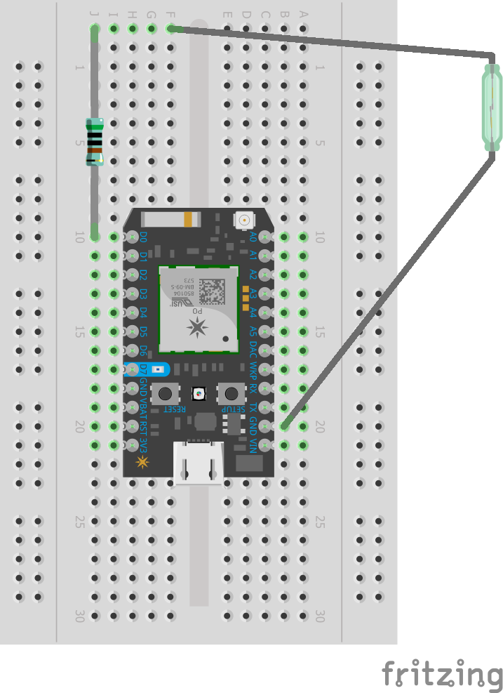
To test that the switch worked, I connected it to the Photon using jumper wires. The configuration was as follows:
One arm of the reed switch was connected to the ground (GND) pin on the right-hand side of the Photon. The other arm was connected to the breadboard using a jumper wire, which was itself connected to the digital D0 pin using a 5kΩ resistor.
I then deployed the following code to my Photon using the Particle Web IDE:
#define PIN_REED D0
void setup() {
   pinMode(PIN_REED, INPUT);
   Serial.begin(9600);
}
void loop() {
   Serial.println("Reed: " + String(digitalRead(PIN_REED)));
   delay(1000);
}
My script assumes that the reed switch connects to digital pinD0. If you want to change this, you will need to editPIN_REED.
With the code running, I wanted to be able to see the current value being returned by the switch via the serial values being printed in the loop function. I used the Particle CLI to do this, and received the following values through it:
Reed: 0
Reed: 0
...
Reed: 1
Reed: 1
Where 0 indicates that the door is closed, and 1 indicates that it is open. If you are using a N/C switch, these numbers will be reversed.
I haven't tested this myself, but the output will probably be the opposite way around if you are using N/C reed switches. That is, a closed door would probably produce output1, and0for open.
Attach Temperature Sensor
Next, I placed the temperature sensor inside the fridge, below one of the shelves in a place that I felt would minimise its being damaged, as it is clearly visible for those who use the fridge. I secured its cabling to the wall of the fridge and used some white tack to keep the sensor steady.
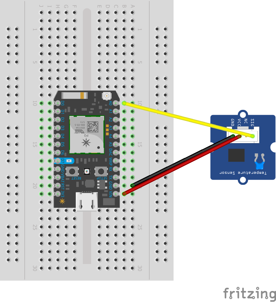
To test that the sensor worked, I connected it to the Photon using jumper wires. The configuration was as follows:
The VCC was connected to the VIN pin on the Photon to give the sensor 5 volts. It was grounded using the GND pin on the right-hand side, and SIG was connected to the analog pin A0.
To test that the sensor works, I deployed the following code onto my Photon using the Particle Web IDE:
/*
* Based on the code from:
* https://raw.githubusercontent.com/SeeedDocument
*     /Grove-Infrared_Temperature_Sensor/master/res
*     /MeasureTemperature.zip
*
* For more information:
* http://wiki.seeedstudio.com
*     /Grove-Infrared_Temperature_Sensor/
*/
#include <math.h>
#define PIN_TEMP A0
#define CALIB 0
const long RES[100] = {
   318300,302903,288329,274533,261471,249100,237381,
   226276,215750,205768,196300,187316,178788,170691,
   163002,155700,148766,142183,135936,130012,124400,
   119038,113928,109059,104420,100000,95788,91775,
   87950,84305,80830,77517,74357,71342,68466,65720,
   63098,60595,58202,55916, 53730,51645,49652,47746,
   45924,44180,42511,40912,39380,37910,36500,35155,
   33866,32631,31446,30311,29222,28177,27175,26213,
   25290,24403,23554,22738,21955,21202,20479,19783,
   19115,18472,17260,16688,16138,15608,15098,14608,
   14135,13680,13242,12819,12412,12020,11642,11278,
   10926,10587,10260,9945,9641,9347,9063,8789,8525,
   8270,8023,7785,7555,7333,7118,6911};
void setup() {
	Serial.begin(9600);
}
void loop() {
	float temp = getTemp(10);
	Serial.println("Temp (Celsius): " + String(temp));
	delay(1000);
}
float getTemp(int sample) {
	int signal = 0;
	float tempSum = 0;
	float temp;
	float R;
	for(int i = 0; i < sample; i++) {
		tempSum += analogRead(PIN_TEMP);
		delay(10);
	}
	temp = tempSum / sample * 1.1 / 1023;
	R = 2000000 * temp / (2.50 - temp);
	signal = binSearch(R);
	return signal-1 + CALIB + (RES[signal-1] - R) /
	       (RES[signal-1] - RES[signal]);
}
// For measuring the surrounding temperature
float binSearch(long x) {
	int low, mid, high;
	low = 0;
	high = 100;
	while (low <= high) {
		mid = (low + high) / 2;
		if(x < RES[mid])
			low = mid+1;
		else
			high = mid-1;
	}
	return mid;
}
My script assumes that the temperature sensor connects to analog pinA0. If you want to change this, you will need to editPIN_TEMP.
With the code running, I received the following values through the Particle CLI:
Temp (Celsius): 1.72761
Temp (Celsius): 1.70890
Temp (Celsius): 1.72013
...
The temperature value might initially start off high as the sensor has just been placed into the fridge. In time, it should decrease until it reaches the temperature being maintained by the fridge.
Attach Buzzer
I attached the buzzer to the top of the fridge and taped it down.
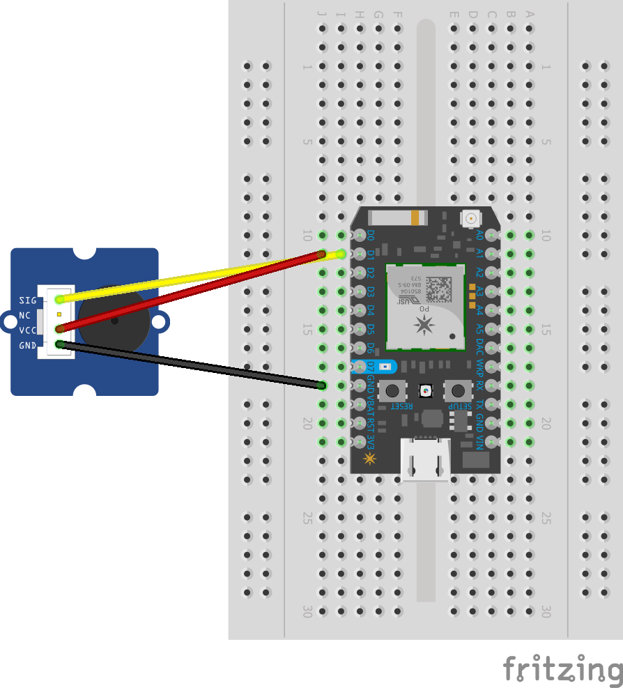
To test that the actuator worked, I connected it to the Photon using jumper wires. The configuration was as follows:
I grounded the buzzer using the GND on the left-hand size of the Photon, as the rightmost GND is reserved for the reed switch and temperature sensor from before. I connected both the VCC and SIG connections to the digital D1 pin. This is because the buzzer only requires power when you actually want it to produce noise. Therefore, connecting both to the same pin works nicely and reduces complexity.
I tested it using code that would repeatedly sound the buzzer, as shown below:
#define PIN_BUZZER D1
void setup() {
   pinMode(PIN_BUZZER, OUTPUT);
}
void loop() {
   digitalWrite(PIN_BUZZER, HIGH);
   delay(1000);
   digitalWrite(PIN_BUZZER, LOW);
   delay(1000);
}
My script assumes that the buzzer connects to digital pinD1. If you want to change this, you will need to editPIN_BUZZER.
If the buzzer is working, you should hear it beep for 1 second, then turn off for 1 second. This will repeat indefinitely.
Attach PIR Sensor
I attached the PIR sensor to the top of the fridge, close to the fridge door. I taped the wires down and used white tack to hold the PIR steady.
To test that the sensor worked, I connected it to the Photon using jumper wires. The configuration was as follows:
I connected its VCC pin to the 3v3 pin, as this sensor does not require the 5 volts that the temperature sensor requires. It was grounded using the GND pin to the left-hand side of the Photon. Its SIG pin was connected to the digital D2 pin.
I tested it using the following code:
#define PIN_PIR D2
void setup() {
   pinMode(PIN_PIR, INPUT);
   Serial.begin(9600);
}
void loop() {
   Serial.println("Motion: " + String(digitalRead(PIN_PIR)));
   delay(1000);
}
My script assumes that the PIR sensor connects to digital pinD2. If you want to change this, you will need to editPIN_PIR.
With the code running, I received the following values through the Particle CLI:
Motion: 1
Motion: 1
Motion: 1
...
Motion: 0
Motion: 0
Motion: 0
When the value is 1, it means that motion had been detected, and 0 otherwise.
Summary
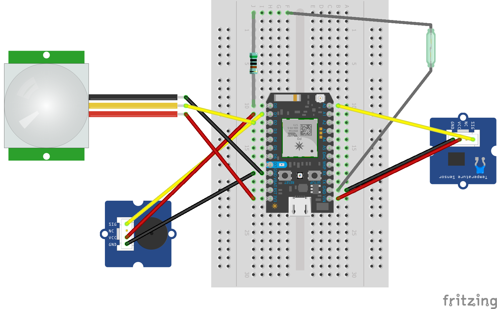
If we connect all of the above sensors/actuators and combine the configurations from their individual schematics, the smart fridge should be configured as follows:
In the real world, it should look something like this:
It's a bit of a mess - but it works!™
Deploy CodeNow that I am satisfied that everything works in isolation, and I have all of the sensors and actuators connected to the Photon, the final step is to deploy the main script to make the smart fridge work. This is the Smart Fridge Script that can be found in the Code section of this tutorial.
When you deploy the script, the serial output should be a stream of the latest sensor data, for example:
Reed: 0
Reed: 0
PIR: 1
Reed: 0
Reed: 0
PIR: 1
Temp (Celsius): 0.154182
...
By adjusting the send_data function in the script, you can enable the code to send the sensor data to an external source of your choosing.
In the video below, I demonstrate what happens as the smart fridge enters low-power mode.
A few seconds into the video, the smart fridge beeps, and the Photon's light turns white, indicating that the Wi-Fi adapter has been switched off. About 15 seconds later, I enter the room and take out a jug of water from the fridge. In doing so, the Photon returns to its normal (non-low-power) mode, as indicated by its reconnecting to the room's Wi-Fi router.
In the future, I will:
- Consider more sensors to add to the setup, such as an e-ink or LCD display that displays the current temperature. The screen could also deactivate when in low-power mode.
- Move the setup away from the breadboard and mount a printed circuit board (PCB) to the fridge instead, to clean up the messy setup that I have currently.
- Connect it to a wider system and other external services (à la IFTTT).


Comments