People who are completely blind or have impaired vision usually have a difficult time navigating outside the spaces that they're accustomed to. In fact, physical movement is one of the biggest challenges for blind people, explains World Access for the Blind. Traveling or merely walking down a crowded street can be challenging. Because of this, many people with low vision will prefer to travel with a sighted friend or family member when navigating unfamiliar places.
Also, blind people must memorize the location of every obstacle or item in their home environment. Objects like beds, tables and chairs must not be moved without warning to prevent accidents. If a blind person lives with others, each member of the household has to be diligently about keeping walkways clear and all items in their designated locations.
How It Works:The Latitude and Longitude is obtained from the embedded GNSS, thanks to the Sony's Spresense Board which has an integrated GPS support. The input from the blind person is obtained using the Voice recognition module. The Audio signal is sampled and then computed.
Depending on the place mentioned by the Visually challenged person, The Geo-Coordinates of the destination is extracted from the Google's Firebase.
Upon this comparison, the controller drives the voice playback unit for providing voice navigation to the user. Predefined voices are stored in the SD card as navigating commands to the blind persons.
We can store the destination values for each voice of spoken command in the Firebase for recognizing the destinations.
Ultrasonic sensor detects the obstacle in the way onto the destination, so that microcontroller gets it and alerts the visually impaired persons.
Hardware BuildFirst of all, I would like to thank Hackster.io and Sony Corporation for supporting this project with the Amazing Spresense Board. I really felt informative using this board and able to achieve some of the complex projects integrated within a single PCB.
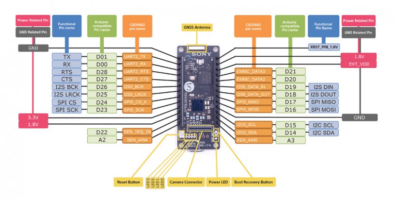
Sony's Spresense Board:
Spresense is a compact development board based on Sony’s power-efficient multicore microcontroller CXD5602. It allows developers to create IoT applications in a very short time and is supported by the Arduino IDE as well as the more advanced NuttX based SDK.
Features:
- Integrated GPS - The embedded GNSS with support for GPS, QZSS and GLONASS enables applications where tracking is required.
- Hi-res audio output and multi mic inputs - Advanced 192kHz/24 bit audio codec and amplifier for audio output, and support for up to 8 mic input channels.
- Multicore microcontroller - Spresense is powered by Sony's CXD5602 microcontroller (ARM® Cortex®-M4F × 6 cores), with a clock speed of 156 MHz.
Voice Recognition Module:
For this project, I had used the Elechouse V3 Voice Recognition Module. There are several other ways to implement voice recognition in the project, For example, Android phone to Alexa or Raspberry pi. The main reason I chose this module over other options is that I wanted to make this project as simple as possible for beginners and to function independently without relying on other controllers.
You can find more details on the datasheet.
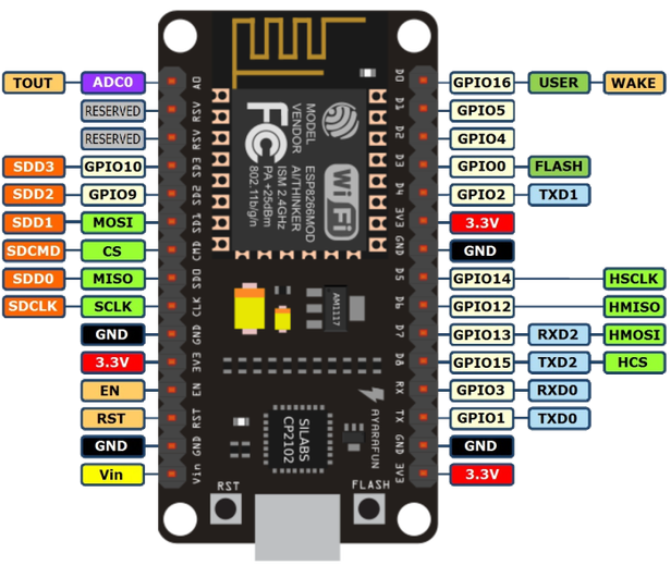
NodeMCU:To connect with the cloud or to get access to Google Maps, it is essential to connect the device to the internet either via Ethernet or Wi-Fi. In our case, since the device needs to be portable, we had implemented with ESP8266, the Wi-Fi module.
NodeMCU is an open-source IoT platform. It includes firmware which runs on the ESP8266 Wi-Fi SoC from Espressif Systems, and hardware which is based on the ESP-12 module.The term "NodeMCU" by default refers to the firmware rather than the development kits. The firmware uses the Lua scripting language. It is based on the eLua project and built on the Espressif Non-OS SDK for ESP8266. It uses many open source projects, such as lua-cjson and SPIFFS.
Features of the ESP8266 include the following:
It can be programmed with the simple and powerful Lua programming language or Arduino IDE.
- USB-TTL included plug & play.
- 10 GPIOs D0-D10, PWM functionality, IIC,and SPI communication, 1-Wire and ADC A0,etc. all in one board.
- Wifi networking (can be used as anaccess point and/or station, host a webserver), connect to theinternet to fetch or upload data.
- Event-driven API for network applications.
- PCB antenna.
- Wireless connectivity: Wi-Fi: 802.11 b/g/n
- Peripheral interfaces
- Security
- Power management
To work with ESP8266, we need to regulate a 3.3V supply. This can be done either by directly connecting it to the Spresense Board or using a voltage regulator externally.
Here we stream the data to the Cloud via MQTT protocol. With the data set, certain algorithms are implemented to make use to the Google Maps API.
Step 1: Getting Started with Sony's Spresense Board and NodeMCUIn this project, we will be interfacing with data such as Latitude, Longitude, Altitude, Time, Location of the Source and Destination, and firmware that publishes the data from the sensors.
Connect the Tx and Rx pins of the Spresense Board to NodeMCU board's USART.
Spresense board ESP8266 Module
Tx -> Rx
Rx -> Tx
3.3V -> 3.3V
GND -> GND
Step 2: Interfacing Other SensorsInterfacingVoice Recognition Module:
There are two ways to use this module
- using the serial port
- through the built-in GPIO pins
This module (V3) has the capacity to store up to 80 voice commands each with a duration of 1500 ms. Although it will not convert your commands to text, it compares the input signal with an already recorded set of voices which ultimately overcomes the language barriers. We can record the required command in any language or literally any sound can be recorded and can be used as a command. So we need to train it first in order to let it recognize any voice commands.
Connection:
Spresense board Voice Module
Tx (D3) -> Rx
Rx (D2) -> Tx
5V -> 5V
GND -> GND
Then install the Elechouse V3 Voice Recognition Module library
With the vr_train_sample example, we train the sound patterns and then implement it with the project.
You can find more details on the datasheet.
Interfacing Ultrasonic Sensor:
The ultrasonic sensor uses sonar to determine the distance to an object. Here’s what happens:
- The transmitter (trig pin) sends a signal: a high-frequency sound.
- When the signal finds an object, it is reflected and the transmitter (echo pin) receives it.
Connection:
Spresense board Ultrasonic Module
D9 -> Trig
D8 -> Echo
5V -> 5V
GND -> GND
Then install the SR-04 Ultrasonic Module library
With the demo example, we can determine the patterns and then implement it with the project.
Step 3: Uploading the FirmwareBefore uploading the firmware, we have to create a bus to connect Spresense Board with the NodeMCU Board.
Connect the Tx and Rx pins of the Spresense Board to NodeMCU board's USART.
Spresense board ESP8266 Module
Tx -> Rx
Rx -> Tx
3.3V -> 3.3V
GND -> GND
Once the connection is done upload the code for sensors using Arduino IDE.
The procedure for NodeMCU will be discussed in the upcoming session.
The code is added the GitHub Repository which can be found in the code section.
Step 4: Getting coordinates and Processing audioGPS Data:
NMEA Message Structure
To understand the NMEA message structure, let’s examine the popular $GPGGA message. This particular message was output from an RTK GPS receiver:
$GPGGA,181908.00,3404.7041778,N,07044.3966270,W,4,13,1.00,495.144,M,29.200,M,0.10,0000*40All NMEA messages start with the $ character, and each data field is separated by a comma.
GP represent that it is a GPS position (GL would denote GLONASS).
181908.00 is the time stamp: UTC time in hours, minutes and seconds.
3404.7041778 is the latitude in the DDMM.MMMMM format. Decimal places are variable.
N denotes north latitude.
07044.3966270 is the longitude in the DDDMM.MMMMM format. Decimal places are variable.
W denotes west longitude.
4 denotes the Quality Indicator:
1 = Uncorrected coordinate
2 = Differentially correct coordinate (e.g., WAAS, DGPS)
4 = RTK Fix coordinate (centimeter precision)
5 = RTK Float (decimeter precision.
13 denotes number of satellites used in the coordinate.
1.0 denotes the HDOP (horizontal dilution of precision).
495.144 denotes altitude of the antenna.
M denotes units of altitude (eg. Meters or Feet)
29.200 denotes the geoidal separation (subtract this from the altitude of the antenna to arrive at the Height Above Ellipsoid (HAE).
M denotes the units used by the geoidal separation.
1.0 denotes the age of the correction (if any).
0000 denotes the correction station ID (if any).
*40 denotes the checksum.
The $GPGGA is a basic GPS NMEA message. There are alternative and companion NMEA messages that provide similar or additional information.
Here are a couple of popular NMEA messages similar to the $GPGGA message with GPS coordinates in them (these can possibly be used as an alternative to the $GPGGA message):
In addition to NMEA messages that contain a GPS coordinate, several companion NMEA messages offer additional information besides the GPS coordinate. Following are some of the common ones:
$GPGSA – Detailed GPS DOP and detailed satellite tracking information (eg. individual satellite numbers). $GNGSA for GNSS receivers.
$GPGSV – Detailed GPS satellite information such as azimuth and elevation of each satellite being tracked. $GNGSV for GNSS receivers.
$GPVTG – Speed over ground and tracking offset.
$GPGST – Estimated horizontal and vertical precision. $GNGST for GNSS receivers.
Rarely does the $GPGGA message have enough information by itself. For example, the following screen requires: $GPGGA, $GPGSA, $GPGSV.
Now, Run the GPS code to print the GPS data in NMEA format.
The Following output is computed using the Spresense inbuilt GPS sensor.
Voice Calibration:
Once after uploading the Sample_train.ino file, Open the Serial monitor.
You can find the list of command that is supported by this firmware.
Type "settings" in the textbox and click send to view the Baud rate, PWM, and other parameters related to the sampling of the voice signal.
To Calibrate the voice sample, type the command sigtrain "index" "key", where the Signature training is involved, Index refers to the index of the records the module can store (in this case, the module can store the maximum of 80 samples) and the key refers to the Reference name given to that particular voice sample.
In the below image, I have created a voice sample for the word "HOME"
The Next voice sample is stored in index 1 with the key "Restaurant"
To test the voice samples stored, type the command load "index1" "index2"
For this example, I've stored upto index 2.
With the above command, I've tested the voice samples and the equivalent key is printed on the serial monitor.
Firebase has a ton of features including Real-time Database, Authentication, Cloud Messaging, Storage, Hosting, Test Lab and Analytics, but I’m only going to use Authentication and Real-time Database.
The data from the Sony's Spresense board is transmitted to the NodeMCU. The data acquired by the NodeMCU is being Pub & Subscribe via Firebase account.
Creating a Firebase AccountFirst Login to the Google Firebase and create a new project and and Click "Add project" button to create a new project on Firebase.
Give a name to your project and select your country, Click the Create Project Button Button to start.
Make sure that you note the Project ID which will be needed later, when you program the hardware to connect to the project.
Now click on Continue to get access the database created.
Now Click on Develop -> Database from the side menu, Click the Create Database Button and Start the project in Test Mode as shown below.
Enabling the Firebase will direct you to Data and Rules tab, and verify whether the read and write functions are enabled.
Finally Open Project Settings and copy the Web API Key and the other parameters which will be used in the NodeMCU code.
The Firebase is configured to receive the data from the NodeMCU.
Step 6: I2S on Spresense BoardThe Spresense board supports I2S (Integrated Inter-IC Sound Bus) where the audio is played.
The data from the Cloud intimates the directions such as Turn Left, Turn Right, Walk forward, Destination Reached.
The Audio file is stored in the SD card in the mp3 format.
The Sample script is attached in the Git repository.
Step 7: EnclosureI had used an Acrylic enclosure for this project.
First, I placed all the circuitry inside the enclosure and screw it firmly.
I made a small opening for the Earphone jack and the voice recognition module.
The Ultrasonic sensor is placed either in the hands or head.
Finally, all the screw are firmly mounted and the power cable is inserted via a slot.
Step 8: Let's See It WorkingYou can find the data is being published on the Google Firebase.
This data which is logged can be display on either a website or with a mobile application.
Data on the Cloud
Application to subscribe the cloud data and send the direction details to spresense board.
Give a thumbs up if it really helped you and do follow my channel for interesting projects. :)
Share this video if you like.
Happy to have you subscribed: https://www.youtube.com/channel/UCks-9JSnVb22dlqtMgPjrlg/videos
Thanks for reading!


_3u05Tpwasz.png?auto=compress%2Cformat&w=40&h=40&fit=fillmax&bg=fff&dpr=2)
Comments
Please log in or sign up to comment.