Determining the air pollution throughout the city in real-time is a difficult task. This affects the people's health as well as their mind. Although the government takes steps to prevent air pollution, it cannot be implemented practically.
Air pollution has a serious issue on traffic system. In India, as per the indiatimes report, "Air Pollution Claims More Lives In Delhi Than Road Accidents Every Year!"
Air pollution, which is one of the top ten killers in the world and the fifth leading cause of death in India, is responsible for about 10, 000 to 30, 000 deaths annually in Delhi, a report by the Centre for Science and Environment said on Tuesday.
According to Delhi Traffic Police statistics, 1, 671 people died in road accidents last year. Even taking into account the fact that these figures may be under-reported, air pollution is still far more deadly!
Hardware BuildSTM32 based
Layer:
The Air quality has a strong correlation with the human health. To have a continuous track of the air quality, the monitoring unit can be placed in the vehicles. The data from the sensors are collected and published to the Cloud.
The data from the cloud is extracted using an Android App which gives the information about the level of Air quality at that particular location.
Download the following:
gnat-community-2018-20180523-arm-elf-windows64-bin.exe
or
gnat-community-2018-20180524-riscv32-elf-linux64-bin
The Sensor data is computed using the STM Dev Board and sent to the Cloud. The data such as Temperature, Pressure, Humidity, GPS, Heat, CO2 are fed to the cloud. An Android App lets the user to see the pollution data in real-time.
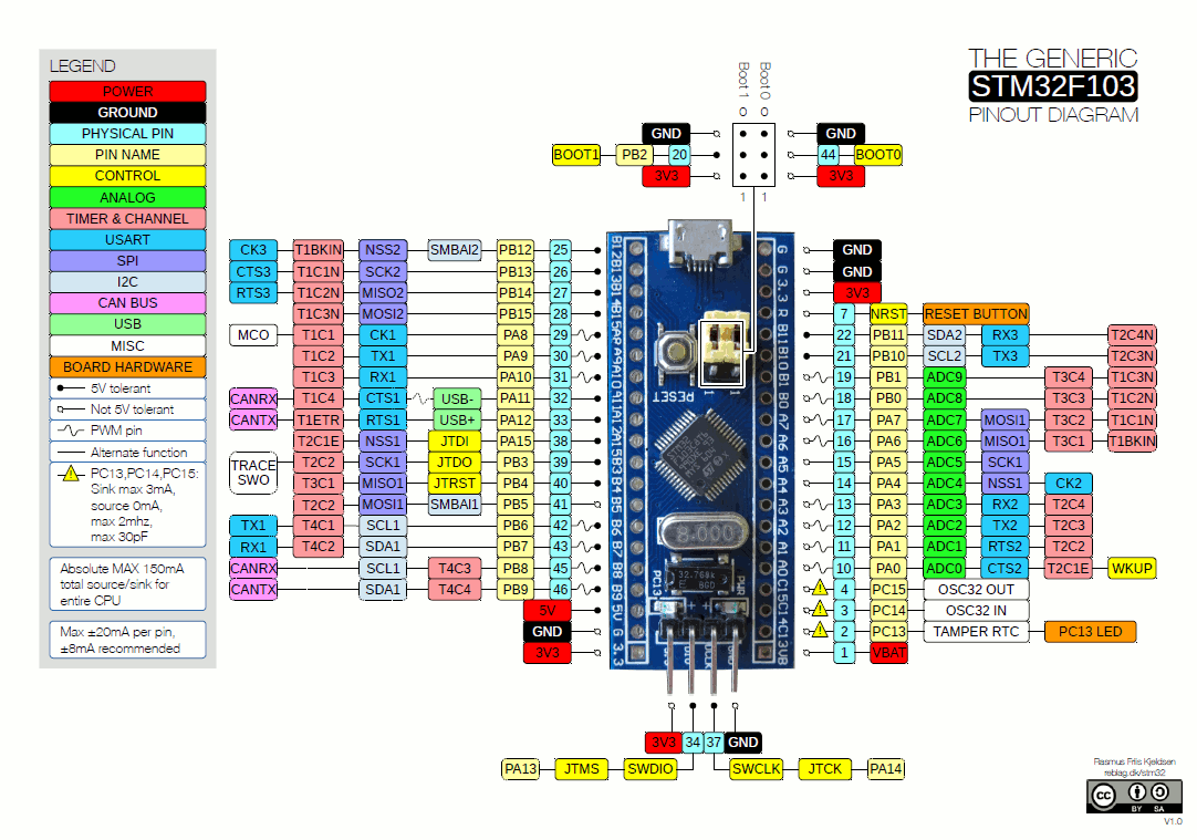
Basic Hardware ComponentsSTM32 Blue Pill Board:
Blue pill is the nickname given to the most popular, ultra-cheap and compact STM32F103 board.
It has better availability than the Red Pill and has been around longer than the Black Pill. See also the very similar RobotDyn Black Pill.
Features:
- Board: Generic STM32F103 Series
- Board part number: BluePill F103C8
- Serial Interface: Enabled with generic Serial
- Flash Memory Size: 64k (you can try 128k; most boards are sold as 64k but in fact have 128k of flash)
- Upload method: ST Link
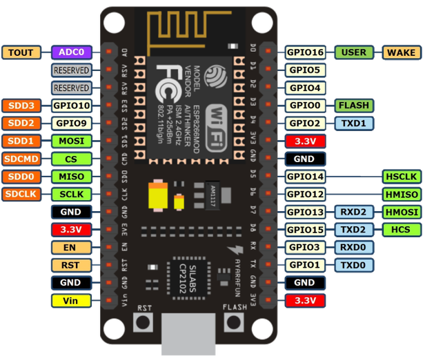
NodeMCU:
NodeMCU is an open source IoT platform. It includes firmware which runs on the ESP8266 Wi-Fi SoC from Espressif Systems, and hardware which is based on the ESP-12 module.The term "NodeMCU" by default refers to the firmware rather than the development kits. The firmware uses the Lua scripting language. It is based on the eLua project, and built on the Espressif Non-OS SDK for ESP8266. It uses many open source projects, such as lua-cjson and SPIFFS.
Features of the ESP8266 include the following:
- Can be programmed with the simple and powerful Lua programming language or Arduino IDE.
- USB-TTL included, plug & play.
- 10 GPIOs D0-D10, PWM functionality, IIC and SPI communication, 1-Wire and ADC A0 etc. all in one board.
- Wifi networking (can be used as access point and/or station, host a web server), connect to internet to fetch or upload data.
- Event-driven API for network applications.
- PCB antenna.
- Wireless connectivity: Wi-Fi: 802.11 b/g/n
- Peripheral interfaces
- Security
- Power management:
In this project, we will be interfacing with Temperature sensor, Gyroscope, Accelerometer, Magnetometer, Barometer, Air Quality, Ambient light and a firmware that publishes the data from the sensors.
Connect the Tx and Rx pins of the STM32 Blue pill to NodeMCU board's USART.
Step 2: Interfacing Other SensorsThe Temperature, Humidity, Barometer, Air Quality, Ambient light, Heat level, Soil Humidity, Water flow sensor and the Motor control should be interfaced for this project.NOTE: Most of the sensors are in-built in this NXP kit.
Now we will see how to interface the other sensors with STM32 Blue Pill.
Interfacing DHT11:
The DHT11 sensor detects water vapor by measuring the electrical resistance between the two electrodes. The humidity sensing component is a moisture holding substrate. When water vapor is absorbed by the substrate, the ions are released by the substrate which increases the conductivity between the electrodes. The change in resistance between the two electrodes is proportional to the relative humidity computed. Higher relative humidity(RH) decreases the resistance between the electrodes, while lower relative humidity increases the resistance between the electrodes i.e Relative humidity is inversely proportional to the resistance between two electrodes.
Here we connect the DHT11 temperature and humidity sensor to the digital pin of the STM32.
The analog pin PA0 of STM32 is used for the output signal.
Connections:
STM32 Blue Pill ------------------------------------- DHT11
VCC(3.3v) -> Vcc(3.3v)
GND -> Ground(0V)
PA0 -> Signal
The Temperature and the humidity from the DHT11 is calculated and stored in the variables which will be carried to the next section of the project.
Interfacing BMP280 sensor:
The BMP280 air pressure sensor from Bosch gives the measured air pressure (ambient air pressure) and the ambient temperature as raw values, whereby the output can now be either via I2C or via SPI interface. But also the BMP280 waits with some improvements compared to the BMP180.
The default I2C address of the mapped module is 0x76 and can be changed to 0x77 with a solder bridge on the module.
Here I had used SPI protocol to communicate with Arduino.
With the aid of 12 compensation parameters stored in the sensor, it is possible to determine the atmospheric pressure at the location (station level air pressure), altitude and the ambient temperature from the raw values.
Connections:
STM32 Blue Pill ----------------------------------BMP280
VCC(3.3v) -> Vcc(3.3v)
GND -> Ground(0V)
PB12 -> CS
PB14 -> MOSI
PB15 -> MISO
PB13 -> SCK
Interfacing MPU9250Sensor:
The MPU-9250 is the latest 9-axis MEMS sensor from InvenSense®. This replaces the popular EOL’d MPU-9150. InvenSense® lowered power consumption and decreased the size by 44% compared to the MPU-9150. “Gyro noise performance is 3x better, and compass full scale range is over 4x better than competitive offerings.” The MPU-9250 uses 16-bit analog-to-digital converters (ADCs) for digitizing all 9 axes.
The System In Package (SiP) combines two chips: the MPU-6500, which contains a 3-axis gyroscope, a 3-axis accelerometer, and the AK8963, a 3-axis magnetometer.
Connections:
STM32 Blue Pill ------------------------------- BMP280
VCC(3.3v) -> Vcc(3.3v)
GND -> Ground(0V)
PB8 -> SCL
PB9 -> SDA
Interfacing Air Sensor:
Here I interface MQ5 gas sensor which is a generic gas sensor available in the market which is more suited to detect and determine LPG concentrations.
This module has two output possibilities
- The analog output can be used to detect Gas leakage and to measure the volume of Gas leakage using certain algorithms which are implemented in the firmware and the level of Gas leakage is specified in ppm.
- The digital out can be used to detect Gas leakage. When there is a leakage of gas, an Interrupt is set by the Arduino which indicates the leakage of gas.
The digital pin PA8 of STM32 is used for the Output signal.
Connections :
STM32 Blue Pill -------------------------------MQ5
VCC(3.3v) -> Vcc(3.3v)
GND -> Ground(0V)
PA8 -> Data
Interfacing Light Sensor:
LDR is Light Dependent Resistor. LDRs are made from semiconductor materials to enable them to have their light-sensitive properties. There are many types but one material is popular and it is cadmium sulfide (CdS). These LDRs or PHOTO RESISTORS works on the principle of “Photo Conductivity”. Now what this principle says is, whenever light falls on the surface of the LDR (in this case) the conductance of the element increases or in other words, the resistance of the LDR falls when the light falls on the surface of the LDR. This property of the decrease in resistance for the LDR is achieved because it is a property of semiconductor material used on the surface.
The digital pin PA9 of STM32 is used for the Output signal.
Connections :
STM32 Blue Pill ----------------------------- LDR
VCC(3.3v) -> Vcc(3.3v)
GND -> Ground(0V)
PA9 -> Data
Step 3: Uploading the FirmwareBefore uploading the firmware, we have to create a bus to connect STM32 Blue Pill with the NodeMCU Board.
Connections :
STM32 --------------------------------------- NodeMCU Board
VCC(3.3v) -> Vcc(3.3v)
GND -> Ground(0V)
PB7 (RX) -> TX
PB6 (TX) -> RX
Once the connection is done upload the code for sensors using GNAT IDE.
The procedure for NodeMCU will be discussed in the upcoming session.
The code is added the GitHub Repository which can be found in the code section.
Step 4: Setting Up the Firebase for Publish and SubscribeFirebase has a ton of features including Real-time Database, Authentication, Cloud Messaging, Storage, Hosting, Test Lab and Analytics, but I’m only going to use Authentication and Real-time Database.
The data from the STM32 Blue Pill is transmitted to the NodeMCU. The data acquired by the NodeMCU is being Pub & Subscribe via Firebase account.
Creating a Firebase AccountFirst Login to the Google Firebase and create a new project and and Click "Add project" button to create a new project on Firebase.
Give a name to your project and select your country, Click the Create Project Button to start.
Make sure that you note the Project ID which will be needed later, when you program the hardware to connect to the project.
Now click on Continue to get access the database created.
Now Click on Develop -> Database from the side menu, Click the Create Database Button and Start the project in Test Mode as shown below.
Enabling the Firebase will direct you to Data and Rules tab, and verify whether the read and write functions are enabled.
Finally Open Project Settings and copy the Web API Key and the other parameters which will be used in the NodeMCU code.
The Firebase is configured to receive the data from the NodeMCU.
Step 5: EnclosureI had used an Acrylic enclosure for this project.
First, I placed all the circuitry inside the enclosure and screw it firmly.
I made a small opening for the Light and Temperature sensor.
Finally, all the screw are firmly mounted and the power cable is inserted via a slot.
Step 6: Let's See It WorkingYou can find the data is being published on the Google Firebase.
This data which is logged can be display on either a website or with a mobile application.
Give a thumbs up if it really helped you and do follow my channel for interesting projects. :)
Share this video if you like.
Happy to have you subscribed: https://www.youtube.com/channel/UCks-9JSnVb22dlqtMgPjrlg/videos
Thanks for reading!


_9nsOFQ7ama.png?auto=compress%2Cformat&w=48&h=48&fit=fill&bg=ffffff)


Comments
Please log in or sign up to comment.