I always had the idea to, somehow automate the security of my home. To detect movement is maybe the primary idea that we all have in our heads. So let this device be the first step of our Alarm Series. In this series, we will be not only exploring many ways in which we can detect nonauthorized entry to our homes, but also we will be implementing strategies in which these detections can be processed by a central system.
In this first tutorial, we will use an infrared movement sensor to accomplish our objective. To handle this sensor you need a board with a 5-volt output. That is why we need a board that has that capability. Boards like Arduino Uno or Arduino Nano have it among others. So far so good. But what if we want to decentralize this arrangement and make it remotely managed?
So let's get started.
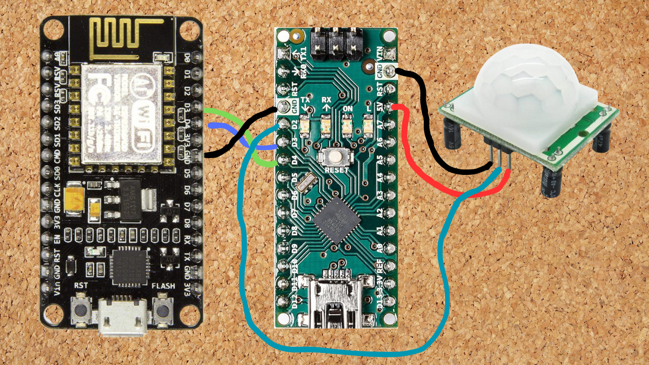
SuppliesAs you can see we will be using a classic movement 5 volts sensor attached to an Arduino Nano or Uno. At the same time, Arduino will be attached to a NodeMCU to send signals to the wifi network. Let's see how to connect them.
ConnectionsNot too complex, the Arduino will exchange information with the NodeMCU through their own D3 and D4 pins. D3 -> D4 and D4 -> D3 reciprocally. Just to establish a serial communication between them. And last but not least the sensor attached to the 5 volts and ground Arduino output. And the data cable to the D2 pin.
Arduino Uno/nano CodeAs you can see the code is very simple. We set up the serial and the software serial for the communication between boards and the pin mode. The loop basically reads if any signal is registered from the pin. And if the signal is HIGH a simple A is sent through the SUART. You can see I leave a print for the unitary test.
NodeMCU CodeThe NodeMCU code is a little bit more complex but not much of a deal. We have been through the setup in previous tutorials, We set the credentials and begin. We added the SUART serial software pretty much the same as the code in the Arduino. The loop waits until a signal is read from the SUART. Once available, we read it and print it. Bear in mind you can remove this, is just for testing. Finally, we send a UDP package with an alerting string.
Upload StepsVery important! you will have to detach the D3 and D4 cables to be able to upload the code to each board. Once the code is uploaded to each board then you can reconnect the cables. If you want to do a halfway test to check how the sensor works or how the NodeMCU connects to the wifi, test their functionality separately. Once you are sure that all is working well, you can go ahead with the assembly.
UDP Client Server TestOnce you have it assembled you will need to test it. So you will have to revisit our UPDClientServer. But bear in mind you can develop your own UDP server in any language or just find one out there.
The SensorBear in mind you can find many kinds of movement sensors. You will find some of them with other voltage requirements. Also, you can take a look at the microwave motion sensor as an alternative. Raka will be playing around with those in future tutorials.
NextSo as you may ask your selves. Why this complex configuration, why use two boards? And that would be a fare question. The answer is that first of all, Raka always wants to test, experiment, and entertain new ideas. He always got interested in serial communication between Arduinos. He feels that in a complex system, this feature will be a good resource to expand the pin limitation of the NodeMCU board. Also, the sensor requires 5 volts which the NodeMCU board does not have. So why not? Also, take into account that you will be able to enhance an old project with simple Arduinos and make it Wi-Fi-borne ;)
But in future updates for this series, I will be building a much more appropriate configuration like I built for the 4 switches tutorial. Having a power source to feed the sensor and the NodeMCU, in this case, should be much smaller. So stay tuned.
Till the next one.


Comments
Please log in or sign up to comment.