

Hardware components | ||||||
 |
| × | 1 | |||
 |
| × | 1 | |||
 |
| × | 1 | |||
 |
| × | 1 | |||
Software apps and online services | ||||||
| ||||||
 |
| |||||
This project is to alter the intensity of the LED automatically according to the surronding light intensity by the LDR sensor. This is done with the python code. The readings of the LDR are mapped to the range of the intensity of the LED and the variable output is generated using Pulse Width Modulation (PWM).If this system is used to monitor the light intensity of a photosensitive environment, such as a certain medicine storage, then a sudden change in light intensity can be harmful. This sudden change is detected using Z-score analysis and an alert system has created in Twilio to send a SMS alert.
2.AUTOMATED CONTROLLINGOF LED :
In this section we study the 'AUTO' functionality of the project i.e. automated change of the intensity of the LED based on the brightness of the surroundings. The brightness of the surroundings is measured using LDR.
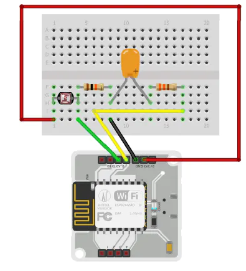
2.1Circuit Connections for LED and LDR
Given below are the circuit connections of LED and LDR with the bolt module for automated LED intensity based on the brightness of the surroundings.
The input from the LDR is taken at analog pin A0 and the output to the LED is written at digital pin 0. LDR terminals don't have polarity. The power supply to the LDR is given using 3.3V pin of the bolt module. The resistance across LDR changes with change in light intensity falling on it. Since the Bolt Module cannot read resistance values, but it can read voltage values, hence a voltage divider circuit is made and the input to the Bolt module is the voltage across 10k resistance (since it is connected between an LDR terminal and ground) which depends on the resistance across LDR. The longer terminal of the LED is connected to the higher potential and the shorter terminal to the lower potential. Here the shorter terminal is connected to ground and the longer terminal is connected to the digital pin 0 through a series 330k resistor. The digital pin 0 output (dependent on LDR/A0 pin input) acts as the power supply for the LED and hence determines. its intensity.
2.2Connectingbolttocloud:
First we have to connect the bolt to the cloud.After connecting to clocd the device will be online.
The above picture will ensure that the device is online.
Then go to API section to know about the API value which is used for sending sms alert.
2.3Mapping of LDR values to LED values
The range of values of the LDR are from 0 to 1024 and that of the LED is from 0 to 255. As evident, one to one mapping is not possible but an approximate 4:1 mapping can be done. It is done as follows:input_to_LED = 255 - (output_from_LDR / 4)The output from LDR is subtracted from 255 (maximum intensity of LED) because the mapping must be done inversely i.e. more brightness in the surroundings must correspond to less brightness of the LED.
2.4Detection of Sudden Change in Light Intensity (Z-Score Analysis)
Z-score analysis is used for anomaly detection. Anomaly here means a variable's value (light intensity of the surroundings) going beyond a certain range of values. The range of values is called bounds (upper bound and lower bound). These bounds are calculated using the input values, frame size and multiplication factor. The frame size is the minimum number of input values needed for Z-score analysis and the multiplication factor determines the closeness of the bounds to the input values curve.
Given above is the formula to calculate the bounds. Here the input is represented as 'Vi', 'r' denotes the frame size and 'C' is the multiplication factor. Firstly we calculate the mean (Mn) of the input values (for every new input, the mean is calculated again). The variation of each input value (from the mean) is given as (Vi - Mn)^2. The Z-score (Zn) is calculated as shown above ( square root of the mean of the variation of each input value multiplied by the multiplication factor). The bounds are represented as 'Tn' and the upper bound is calculated as (Vi + Zn) and the lower bound is calculated as (Vi - Zn).
The frame size and multiplication factor are determined using trial-and-error method.
2.5Creating Twilioaccount:
Go to the twilio website and create a account using the mail id which you have used to create the cloud.
After creating a trial version in twilio make sure that you have given necessary details asked and enter the mobile number which you like receive the alert sms.
The above page will appear after completing all the above mentioned steps.
Note down the SID number and AUTH TOKEN for writing in the python code.
AlertSMSFromTwilio:


Comments