

Hardware components | ||||||
 |
| × | 1 | |||
_ztBMuBhMHo.jpg?auto=compress%2Cformat&w=48&h=48&fit=fill&bg=ffffff) |
| × | 1 | |||
| × | 1 | ||||
 |
| × | 1 | |||
 |
| × | 1 | |||
Software apps and online services | ||||||
 |
| |||||
For part 1 of this series, covering how the firmware is designed and implemented, please see this Hackster Post.
For part 2 of this series, covering the use of the I/O Expander to control 7-segment displays, please see this Hackster Post.
Keyboards and keypads serve as one of the largest connections between humans and computing devices, both big and small. Adding keypad or key-array functionality to a project can simplify interactions with the system. While keypads are simple devices, they require a lot of I/O to be used. Instead of eating up lots of I/O on the main microcontroller (MCU), a small I/O expander could be used in its place to perform this task – saving I/O lines while not compromising on features.
The PIC16F15244 family is made up of simple 8-bit MCUs that can offload this task from the main MCU. The firmware used to create the keypad in these examples is the “Advanced I2C I/O Expander” without any modifications.
Example CodeImportant: Before continuing, be sure to program the PIC16F15244 device with the “Advanced I2C Expander” Code Exampleand install the communication library (located in the same repository).
The Arduino compatible library (not associated with or affiliated with Arduino), along with the required firmware for the PIC16F15244 family device is available on Github. Inside the Github repository, there are 2 software examples:
- active_keypad - Demonstrates the active method for scanning a keypad. Prints out the ASCII equivalent of the key pressed to the serial terminal.
- lockBox - Demonstrates the passive method for scanning a keypad by implementing a simple reprogrammable “lock”.
Important: Program the device before connecting RA0 and RA1 to GND.
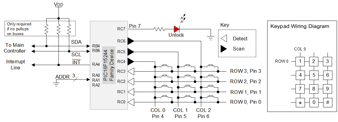
What is a Keypad Scanner?First, an understanding of how keypads are constructed is required. Consider the diagram of a 3x2 keypad, with 6 buttons.
To detect a keypress, one of the lines (ROW or COL) must be monitored for a change in logic level. Selecting which direction to monitor is a developer decision, but generally the more inputs used, the more efficient the keypad scan is due to the fewer possible keys. In the case of the 3x2, the columns would be the better choice to monitor while the ROWs are scanned.
Note: ROW and COL can be switched depending on the configuration of the keypad. In the sample code, the ROWs are monitored while the COLs are scanned.
The next step in the process is to determine what pressed and not pressed are in terms of logic levels. By using the weak pull-up resistors internal to the part, the column lines are defined at a logic ‘1’ when no button is pressed. Since a logic 1 represents not pressed, then a logic 0 must indicate a button press.
One of the challenges with this configuration is determining which key has been pressed. If the top-left button is pressed, then COL 0 will go to a logic 0. The problem is that there are two possibilities for COL 0 – the top left or the bottom left button could both create the event.
To distinguish between the two, one of the ROWs must be a logic 1, which would not hold COL 0 at logic 0. Thus, by knowing which ROW is at 0 and which is at 1, the correct button can be determined. The differences in determining this form the basis of the passive and the active scanner, which are analogous to interrupt driven versus polling based detection.
Important: A weak pull-up should be used to generate the “logic 1”, or use a current-liming resistor in series with all scanned outputs. Otherwise, pressing two buttons at the same time could cause a short circuit.
Passive ScannerThe passive scanner works by setting all ROWs to a logic 0. When a negative edge occurs on an I/O line (indicating a button press), then the code selectively turns on the ROWs (via the weak pull-ups) until the button is found. The advantage of this approach is that the I/O expander can remain in sleep until the interrupt occurs. Figure 3 shows the waveform generated by the passive scanner searching for an event.
An active scanner, by contrast, does not use the interrupt detection abilities of the I/O lines. Periodically, a single ROW is set to 0 to detect any buttons that are currently pressed on the keypad, then returned to a logic 1. The next ROWs are scanned in the same manner. The benefit of this configuration is that multiple key presses and key holds can be detected. The image below shows the normal operating mode of the active scanner. Each row is sequentially dropped to 0 to search for events, then returned to 1 when complete.
Choosing a Method
Deciding on the optimal method to scan the array is dependent on the requirements of the system. For instance, the active scanner can detect multi-key presses and key holds, while the passive scanner can only detect a single key. However, the passive scan is a lower power design since the I/O expander sleeps until the button is pressed, or the device is communicated with. In addition, the passive scan is more efficient to implement for the main MCU, due to its interrupt driven design.
Lockbox ExampleThe passive keypad scan technique was used to create a simple keypad lock, since it is assumed each key is a single event – i.e. key holds are not used. The lockbox is also more power efficient than the passive scan, which is important for battery powered applications.
Each button press on the keypad is converted into the equivalent character on the keypad and passed into a small finite state machine with three states: LOCKED, UNLOCKED and NEW_CODE.
In the LOCKED state, the LED is off, and the user is entering a code. When the code matches the stored code, then the LED is turned on, the counter is reset and the machine transitions to the UNLOCKED state.
In the UNLOCKED state, the LED is turned on to indicate the lock is open. To lock the door (and move to the LOCKED state), the * key must be pressed. To enter a new code, the # key is pressed instead, which clears the former code from RAM and transitions the program to the NEW_CODE state.
In the NEW_CODE state, a new code sequence is entered by the user. The code can contain 0 through 9 and #, however it cannot contain *. Pressing the * key or reaching the memory limit for the key code will cause the keypad to move into the LOCKED state. The keycode can be up-to 10 characters long by default and can be increased, if desired. On reset, the default code is 15244#.
Note: Every key press blinks the LED to indicate the keypress was detected.
The active keypad demo demonstrates a method of detecting keypresses through active scanning. The demo can detect up-to four keypresses at a time and prints out which keys were pressed to the serial interface at 9600 baud.
Software LimitationsWithout any modifications to the I/O expander code example, there are a few limitations to the functionality. For instance, no debouncing occurs in the I/O expander. The Schmitt trigger input levels help to reduce the number of bounces but does not remove all of them. The passive scanner function returns 0x00 (Character ‘\0’) if a false event occurs, while the active scanner avoids this issue due to the delay in sampling the lines. Both examples gain a little bit of immunity to contact bouncing due to the delays associated with I2C communication. An easy modification to add debouncing would be to use TMR2 as a single-shot debouncing timer, as documented here.
Additionally, both examples work only if the button is still pressed when the routine runs – the advanced I2C I/O expander firmware does not support key rollover out-of-the-box. However, the firmware of the Advanced I/O expander is available online and can be customized per application.
Concluding RemarksThis series of blog posts is only a starting point in terms of I/O expander applications. There are so many possible applications that this series of posts could go on forever. To recap, the PIC16F15244 device family is an easy-to-use 8-bit general-purpose family of MCUs. The I/O expander applications utilize the hardware serial module to act as an I2C peripheral device which receives or transmits the I/O state, configuration, and other properties. The main benefit of using an MCU to act in this manner is the flexibility in changing the settings, features and behavior in comparison to an ASIC based solution.


Comments
Please log in or sign up to comment.