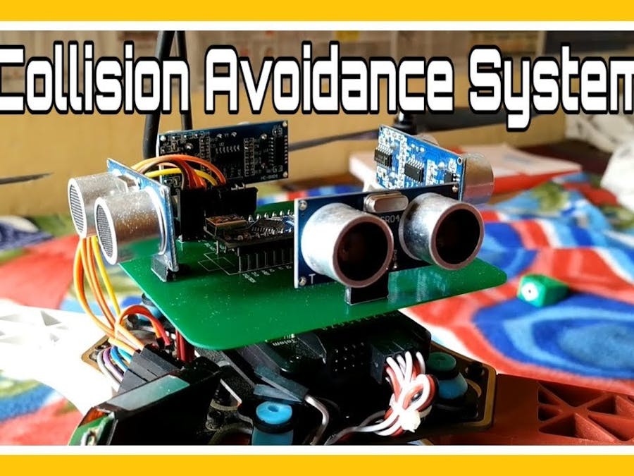
“Collision Avoidance System for Drones”, as the name suggests, protects the drone from collision from any obstacle such as a wall.In day to day life we hear drone crashes which not even cause machine loss as well as a great threat to peoples around. As drones are becoming common these days so it increases the threat of drone failures. So I designed this collision avoidance system to protect people as well as machine loss.
The idea behind the project is too simple. Whenever any obstacle is detected from left side the drone must drift towards right and same in all four directions. By keeping everything really simple I just manipulated the receiver’s signals which are going to the flight controller chip. To detect the obstacle I used “Ultrasonic Sensors”. The project is not perfect but still it is a great step towards a perfect collision avoidance system.
1.3 Explanation of Block Diagram
In the first block in figure 1.1 Rx means Receiver. The Receiver Receives signals from transmitter which is being held by the Pilot. It handover the signal values to the Collision Avoidance Microcontroller. Sensors give values to the Micro Controller. Then microcontroller changes the values of receiver according to the sensors values and sends it to Flight Controller. Flight controller gets values from gyroscope sensor and signals from collision avoidance microcontroller and send signals to electronic speed controller which runs the motors. In this way all system works.
1.4 Applications
1.It can be used in Quadcopters, Hexacopters, Tricopters and Octocopters withoutany major change.
2.It can be used in Self Driving Cars.
3.It can be used in Photographic Drones which work in crowded marriages.
4.It can be used in RC Planes, Boats and other toys.
5.Blinds can also use this by some Modifications.
Circuit Description2.1 Schematics
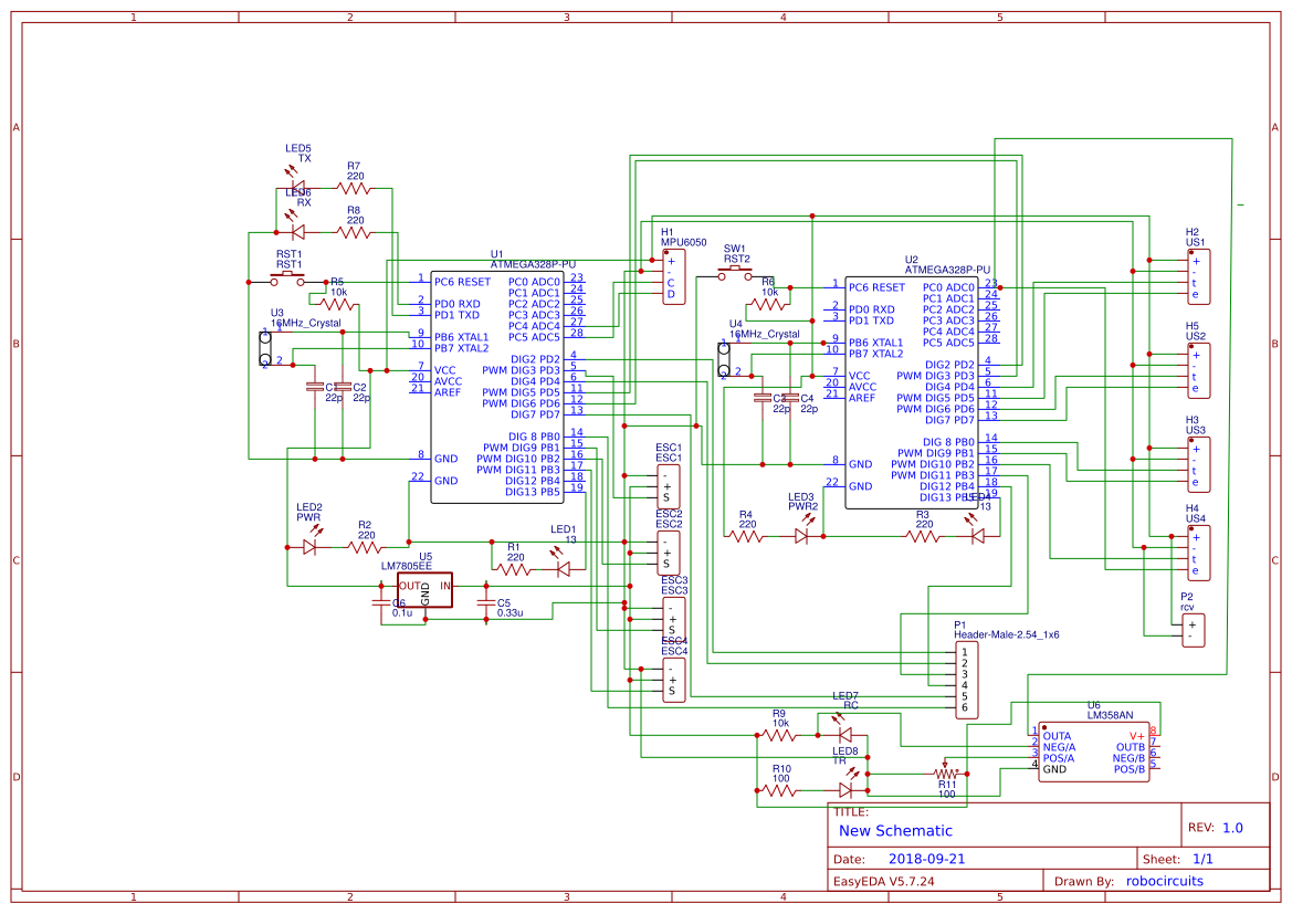
For this project main part are two “atmega328p” Microcontrollers as we can see in Fig 2.1. Each microcontroller is connected with a 16 MHz crystal along with two 22pF capacitors which act as filters. Then both microcontrollers have a LED connected on their power input with a 220ohm resistor to indicate power input, and a reset switch which is connected with a 10K resistor to 5V. IC U1 acts as Flight Controller while IC U2 act as Collision Avoidance controller.
Taking from right 4 Ultrasonic sensors (M2, M3, M4, M5) are connected with 5v and GND to power input From IC U5 “7805” power regulator. Trig and Echo pins of Ultrasonic Sensors are connected to Digital Pins of IC U2.
Header Pins H1 are used for input of Receiver’s Signal. 4 Signals Channel 3, 4, 5, 6 are given directly to Digital Pins of IC U1 while channel 1 and 2 are given to Digital Pins of IC U2 then Channel 1_New and 2_New are taken out from DIG 2 and DIG 3 to IC U1.
The Gyro Sensor MPU6050 is connected with IC U1 using I2C Bus using SDA and SCL Pins to A4 and A5 Respectively.
4 ESC outputs are taken out from Digital 3, 10, 11, 12 pins of IC U1. The Power for this circuit comes from These ESCs so their ground and 5V pins are connected with Pin 2 and Pin 1 of IC 7805 Respectively. Then Pin 3 of IC 7805 is used to power our IC U1, U2, U3, Receiver and our Ultrasonic Sensors.
IC U3 is an Operational Amplifier. It is connected with an IR Pair whose full set act as an Infrared Proximity Sensor which is connected to Analog 0 pin of IC U2.
2.2 Working
The Receiver receives signals from the Transmitter which is held by the pilot on the ground. Receiver has 6 outputs Channel 1, 2, 3, 4, 5 and 6 or Pitch, Yaw, Throttle, Yaw, AUX1 and AUX 2. Channels 3, 4, 5, 6 are directly fed to the flight controller IC while Channel 1 and 2 are fed to Collision Avoidance IC. The Collision Avoidance IC Triggers the first Ultrasonic sensor and Ultrasonic sensor transmit the Ultrasonic sound signal which gets deflected by any obstacle in its range and received by the receiver(as shown in Fig 2.1 below). Then the sensor sets the Echo Pin to HIGH according to the amount of time the sound take to reach back to the receiver of Ultrasonic Sensor. Then that signal is fed to the collision avoidance IC. And also it is reading values from Receiver like (Pitch, Yaw) = (1500, 1500).Whenever say Left Ultrasonic sensor detects any obstacle within 40 cm it will convert Pitch to 1650 and Yaw will remain same, means OUTPUT will be (1650, 1500). If Obstacle is from front it will it will give OUTPUT as (1500, 1350)and same for each side. Then this manipulated signal is fed to the Flight Controller IC which handles the Motor Speed and Drone orientation. That is a simple explanation of how this drone works.
Thanks for Reading


Comments
Please log in or sign up to comment.