


Hardware components | ||||||
| × | 6 | ||||
| × | 1 | ||||
 |
| × | 1 | |||
 |
| × | 1 | |||
 |
| × | 1 | |||
 |
| × | 1 | |||
Software apps and online services | ||||||
| ||||||
The design intent is to enable inferences to be drawn regarding the work being done (i.e., torque applied) by each servo based on the servo current draw (ref).
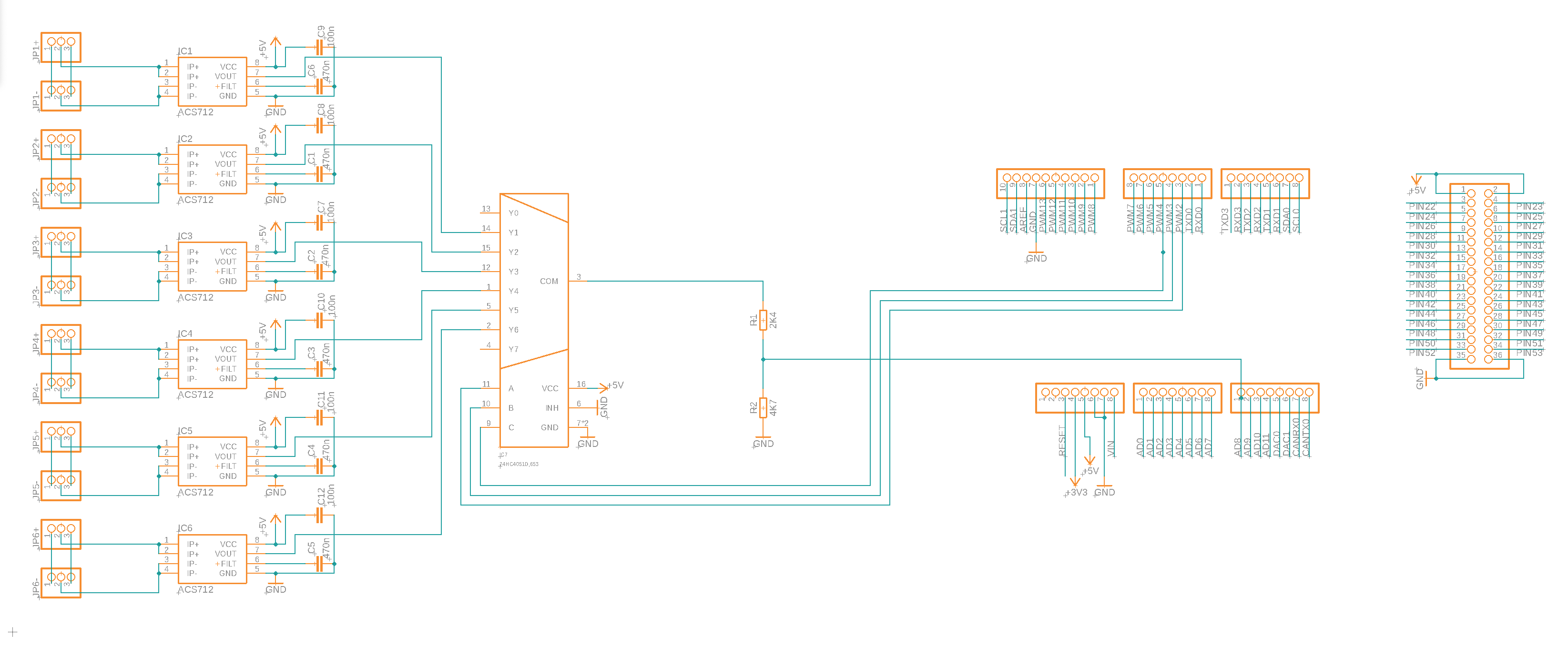
The design builds on the typical application circuit published in the ACS712 datasheet, replicating this six times (one for each servo to be measured). To reduce the number of Arduino pins used from six analog pins down to one analogue common pin and three digital selection pins, a 74HC4051 multiplexer is used.
Both the ICs are powered at 5V, and a voltage divider brings this output down to a safer level for the 3.3V Arduino Due.
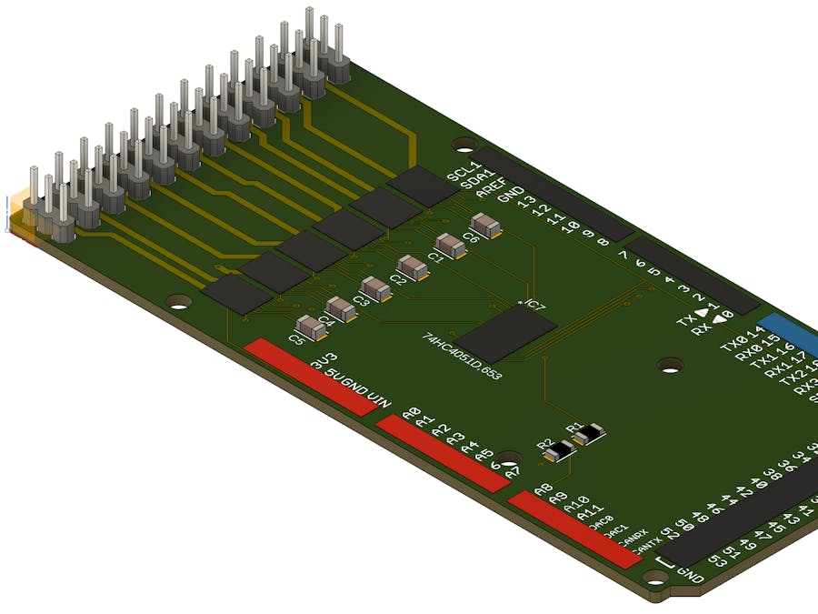
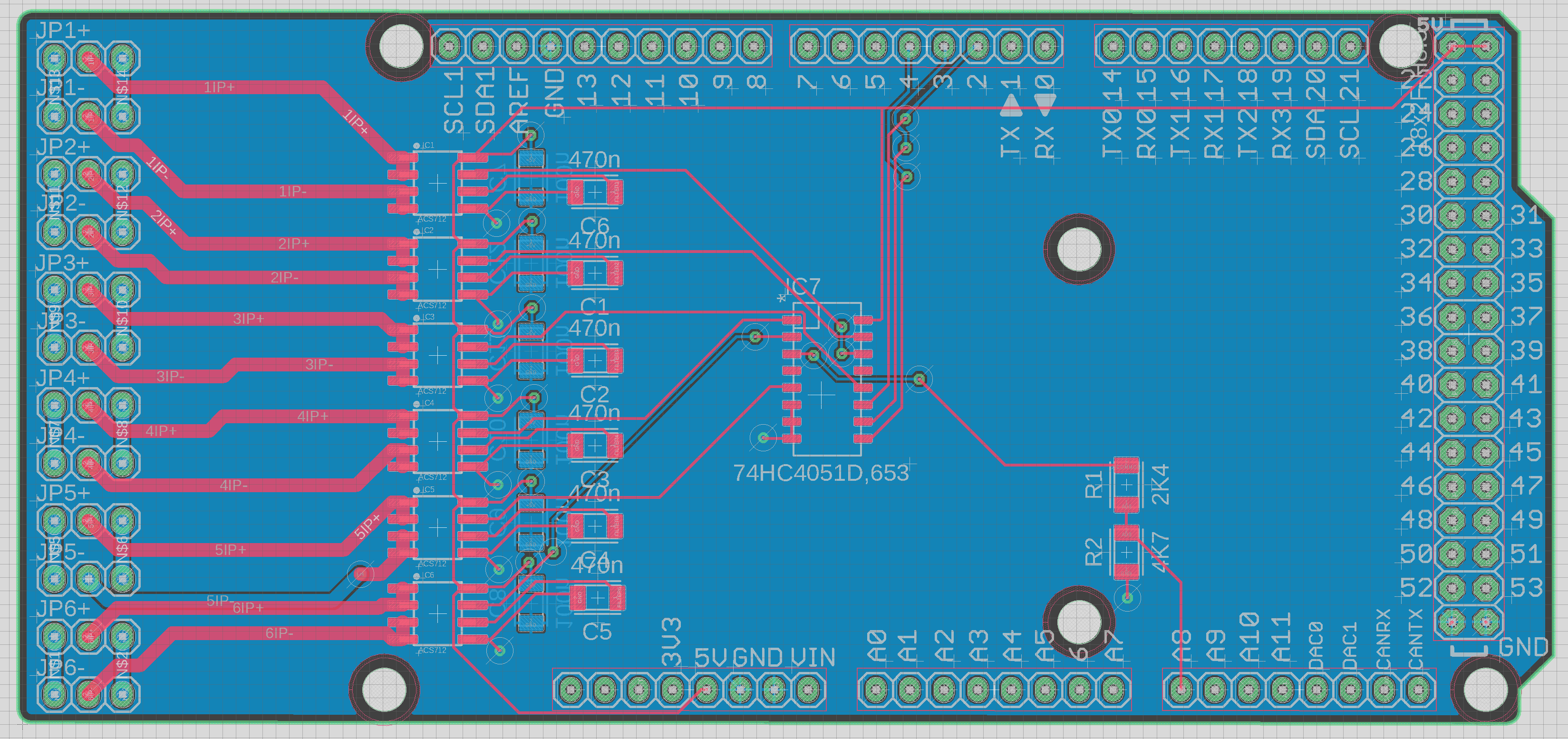
The physical shape of the PCB started with the footprint of an Arduino Due. CAD files for a blank shield are linked in the attachments. The edge of the board which has no pin headers on an Arduino Due was extended out so that three-pin connectors could be added for the six servo input and output connections. By extending the PCB these connectors are outboard and clear of any other stacked shields.
The schematic for the board is in the attachments both as a PDF and as links to CAD files.
The project github repo linked in the attachments section has the CAD and CAM files.
Prototype TestingThe first iteration of prototype testing revolved around the ACS712 sensor. I wanted to check that introducing the output voltage shift from 5V to 3.3V worked as intended. I also wanted to see what value looked good for the filter capacitor on pin 6 of the ACS712.
At different times I used both a commercial ACS712 breakout board and a home built perfboard version. On the perfboard I was able to add the voltage divider and try various values of the filter capacitor.
My test rig used a Gobilda servo programmer to deliver 6V 5A power from a bench power supply along with suitable PWM signals to the servo under test. I powered the ACS712 from an Arduino Due using the 5V pin, but the Arduino wasn't used for anything else in the initial tests, just power.
I used an oscilloscope connected to the ACS712 output to evaluate results and to compare readings for different types of load on the servo.
The second set of prototype testing added the multiplexor to the ACS712 test bed. I wanted to check that no additional noise was introduced to the ACS712 output, and also that driving the 74HC4051 selector pins at 3.3V levels would work OK. This test rig also enabled me to start working on a sample Arduino sketch in parallel to getting the PCB design finalised and the order submitted to PCBWay.
This project was sponsored by PCBWay. It was the first time I had designed a PCB and sent it for manufacture, and I learned a few things along the way. Most of the learnings were newbie issues getting my schematic and PCB design worked up to a good quality level in Fusion 360 computer aided design (CAD) and computer aided manufacture (CAM) software. Once I had the design in Fusion 360, exporting the required Gerber files from the CAM module was very simple.
Uploading the job to PCBWay took a few days - - all down to me, I had to travel on a business trip in the middle of the process. The PCBway website is straight forward and the very many options are documented clearly. Once I had the files uploaded the job moved along immediately to quality control.
Initial estimates for the job were approximately USD$35 for fabrication and the same for assembly, more on this later.
I requested two services on my job, PCB fabrication and also supply and assembly of the surface mount components. PCB fabrication uses gerber and drill files. Assembly requires additional Bill of Materials (BOM file); Pick and Place (PnP / Centroid) files, and other optional design files. The quality review was very quick on the fabrication part of the job, and a day or so on the assembly part. I had made an error on one of the parts selected. The ACS712 library component I had used in Fusion 360 did not contain sufficient CAM information to identify the specific part. I received a clear email from a customer service representative requesting me to confirm the BOM and provide the extra details which was easy to do. I was impressed by the PCBWay customer service, a person available on chat and email was very helpful. All the communication was in English which was essential for me.
This is when the pandemic chip shortage complicated things. All of the online distributors I was familiar with were quoting lead times of more than six months on the ACS712ELCTR-05B-T sensor IC with prices more than AUD$10 for single units. I opted to allow PCBWay to substitute suitable alternatives from other manufacturers and crossed my fingers. PCBWay were able to find a component supplier and lead time of about one month, at a unit cost of USD$4.18. This has obviously made my costs higher, but I think it's a win that PCBWay found a solution for me in the current market.
I was keen to keep track of my first PCB boards, and found that the PCBWay website is very informative. I could track the job through its stages and watch its progress towards completion.
Once the assembly job got to the quality control stage a PCBWay employee contacted me by email with photographs of a board to check that IC orientations were all as anticipated.
The boards arrived ahead of schedule, well packed and are great quality. I soldered on some pin headers and started testing.
The sample sketches (see the Github link below) progressively build up from a minimal example, to more useful examples. The sample sketches are:
- Sample_1.ino: a minimal example, taking a reading from one sensor
- Sample_2.ino: adds in running averages, and Exponential Weighted Moving Average (EWMA) methods to smooth the reading output
- Sample_3.ino: adds the data structures to track all six sensors
- Sample_4.ino: switchs to non-blocking code
The formulaes applied to convert the ADC sample read by the Arduino to a current reading are as follows:
From the ACS712 datasheet:
Ip = (VIOUT - VIOUT(Q)) / SENSITIVITY
To calculate the voltage divider level shift:
Vout = Vin * R2 / (R1+R2)
To convert the ADC sample read by the Arduino into a voltage:
reading(volts) = reading(sample) * reference_voltage / ADC_resolution
Connectors:
- JP[1-6]+ to servo driver / power source
- JP[1-6]- to servo / load
Arduino Pin Usage:
- D2 sensor selector A output
- D3 sensor selector B output
- D4 sensor selector C output
- A8 (input) sensor reading from selected sensor, level shifted to 3.3V
During the course of the build I learned more about the limitations of hall sensors, which are the basis of the ACS712. The accuracy seems to be sufficient for this application, but if I needed to build something more precise in the future I'd probably look at modifying the design to replace the ACS712 IC with simple shunt resistors combined with a suitable amplifier IC (e.g., INA219).
I'll definitely be using PCBWay again, their quality and communications makes their price point very attractive.
BuyI'll be selling my excess boards on Tindie.


_t9PF3orMPd.png?auto=compress%2Cformat&w=40&h=40&fit=fillmax&bg=fff&dpr=2)


_3u05Tpwasz.png?auto=compress%2Cformat&w=40&h=40&fit=fillmax&bg=fff&dpr=2)
Comments
Please log in or sign up to comment.