

Hardware components | ||||||
| × | 1 | ||||
| × | 1 | ||||
| × | 1 | ||||
| × | 1 | ||||
| × | 1 | ||||
| × | 1 | ||||
Software apps and online services | ||||||
 |
| |||||
This iteration continues the project to build a simple robot arm from scratch, and builds on the lessons learned in iteration 2.
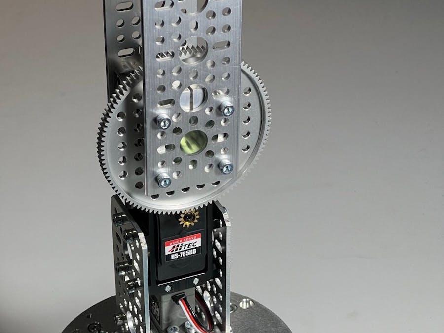
Shoulder Reconstruction SurgeryThe objective in redoing the shoulder joint was to increase the torque output. The new gearbox servo produces 118.8 kg.cm and the revised arm is 40+ cm outboard from the centre of the shoulder shaft. So shoulder torque at the actuator should be ~2.97kg.40cm (increasing from ~0.72kg.30cm in the previous iteration)
The gearbox is supplied with a 32mm OD 39mm length flanged shaft. To allow hub mounting on the reverse face, this was swapped out with a 50mm length unflanged alluminium tube. 1500 Series 1mm Plastic Spacers were used to keep the second hub from touching the gearbox housing.
The shoulder to elbow link is now implemented by two five hole (1123 series) pattern plates. The plates ended up with a seperation of about 49mm. Two 70mm threaded M4 rods covered by spacers provide cross bracing midway up the link.
Above the elbow joint, and below the shoulder joint, the arm remains structurally the same as iteration 1.
An important WARNING is to avoid over driving the Hitec HS-788HB gearbox servo. This servo can rotate seven turns (2826 degrees) and does not have any physical rotation stops. Do not drive the PWM signal below 0.600ms or above 2.400ms otherwise the servo will continuously rotate and the internal potentiometer can detach from the shaft depending on the orientation of the servo.
A generic MPU6050 3-axis gyroscope, 3-axis accelerometer has been added in the actuator / gripper assembly as shown in the photograph. The sensor is I2C connected. The software for Iteration 3 retrieves unprocessed readings from the sensor, but in future iterations I hope to calculate more about the movement at the actuator. As shown in the photo the sensor x-axis is oriented along the end effector (i.e, towards the viewer of the photograph).
The I2C connects to the Wire1 Due port on SDA1 (pin 70) SCL1 (pin 71), 3.3V and GND.
A nine track Pololu QTRX-HD-09A infra-red reflectance sensor array has been mounted getting ready for a future base rotation absolute encoder. Only 8 tracks are planned to be used. Due connections are to pins A0-A7 (eight data channels), 5V, GND, D52 (Even Control), D53 (Odd Control)
The new heavy base stops the robot arm from falling over when moving suddenly. The 70mm hex standoffs open up a suitable space to house the microcontroller and electronics.
Prototype artists's foam board "finger sleeves" have been added to the gripper to extend the finger length, increase grip, increase finger width, and experiment with different shaped designs. When a suitable design is arrived at, future iterations will look at more robust materials.
The Arduino code for the project has really launched in this iteration. Previous iterations used code based on the Adafruit PWM Servo Library examples. This iteration continues on from that start. See the link to project GitHub repository in the Attachment section below. The code is getting updated on a dev branch for the moment, when there is something useful and stable it will be merged to the main branch.
Code design elements that are still a work in progress are:
- finite state machines for arm, joint, sensor and input-ouput (I/O);
- starting with serial monitor I/O, but with th anticipation to also use an interface to the Robot Operating System (ROS) in the future;
- to set up data structures that support future iterations.
Between Iteration 1 and 2 several new servo test methods have been developed and acquired.
A homemade protoboard servo connector breakout is used to insert test points into servo lines. The board has an LED indicator to show when the motor power is live as well as test points on each servo line (5V, GND, PWM Signal). This has been really useful as the oscilloscope remains the PWM test tool of choice.
Gobilda make a servo programmer for their 2000 series servos. This is necessary for changing the servos between default and continuous mode (should that be useful). It also has basic 3-point test modes and sweep modes.
I also purchased a (very) generic eight channel servo test controller board off eBay. It works well. It's pictured above in the Pololu sensor array photos.
Completed ArmAt least for this iteration... It's starting to remind me of a Skutter from Red Dwarf.
The use of the PCA9685 module arose from my first arm project in a progression away from Arduino Uno and Braccio Shield. Uncertainty about powering the servo's separately to the microcontroller made the PCA9685 module a comfortable interim step, which maintained backwards compatability with the Braccio Shield. It strikes me that it's not necessary any longer. The Due has plenty of pins available. Calibrating the PCA9685 adds an extra step, and the PWM output isn't as highly accurate as it could be. Future iterations may move back to directly driving the servo PWM from Arduino Due.


Comments