

Hardware components | ||||||
| × | 1 | ||||
| × | 1 | ||||
Software apps and online services | ||||||
| ||||||
| ||||||
Update March 2022: Like all good iterative designs, things changed during physical testing of the prototype, specifically the torque of the shoulder servo was underspecified in the design below. Also after trying a few COTS options, I wanted to make my own actuator. I'll post the story of the physical prototype build as iteration 2.
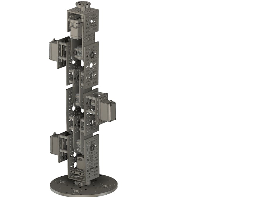
This is the design stage of a DIY robot arm using Gobilda build system. The CAD files provided on the Gobilda web site for each component have been assembled in Autodesk Fusion 360 to create a working digital model of the intended arm design. The project is currently a work in progress and the design hasn't yet been tested by a physical build.
The design is an iteration moving on from my previous Braccio Robot Arm and it's intended that the kinematics not be a great deal different. The MCU and PWM controller will also be an evolution from the Braccio shield, moved to an Arduino Due base, which I'll document in a seperate project.
Gobilda was selected as a metric aluminium build system with good engineering prinicples tested through the STEM educational competition process (FTC).
The goal is to achieve a robust and easily modified platform for learning.
Estimated materials cost (excluding freight) for the Gobilda components at September 2021 is USD$510.
End EffectorAt first the end effector will be a simple off the shelf gripper (pictured below). A subsequent project might be to build one in the gobilda system.
EffectorParts List:
- Gripper unit (see Robot Mechanical Aluminium Gripper in materials list above)
- Gobilda 2000-0025-0002 Dual Mode servo x1
For parts list see attachment.
Link 2 and 3 are identical, just flipped around to alternate the weight of the servos.
For parts list see attachment.
For parts list see attachment.
For parts list see attachment.
The arm will be heavy (just under 4kg) and it's anticipated that the base plate will be attached to a substantial mass or structure to prevent the arm from tipping itself over.
For parts list see attachment.
Anticipated AdjustmentsThe design attempts to reduce the overall arm length as much as possible. To this end the joint clearances between links have been kept small and it's intended to trim the corners of the shoulder angle pattern bracket, and the two elbow pattern plates to clear the joint rotation path. See the circled areas in the figure below.
The base rotation shaft is a little longer than desired and will require trimming to size (trim the non-spline end!).
The CAD modelling has not included every nut and bolt. I intend to order a supply of M4 in various lengths while I figure out the connections.
The model uses M4 threaded standoffs by default. I intend to order a matching quantity of unthreaded spacers. Being able to chose between threaded and unthreaded will be useful as I figure out the nuts and bolts.

_t9PF3orMPd.png?auto=compress%2Cformat&w=40&h=40&fit=fillmax&bg=fff&dpr=2)


Comments