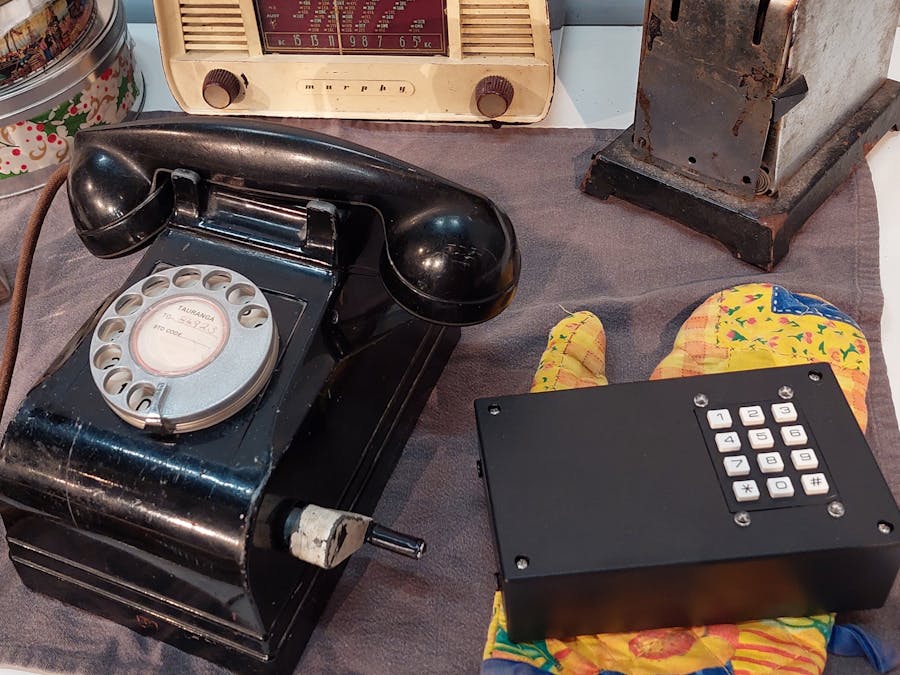
I've been an amateur theatre nut for 50 years and was challenged to make a 1950's party line telephone ring on stage with various ringing cadences for the Pip Hall play "Up North". I used to be a telephone technician for some 20 years in the 70's and 80's, so am familiar with the requirements to make this work: 60VAC at 20Hz. Plus up to ten ringing cadences using Morse code for the letters A, D, J, K, M, R, S, U, W and X. Then I'll be operating this as well as playing the music, the sound effects and operating the lighting, so I'll have my hands full during the performances too!
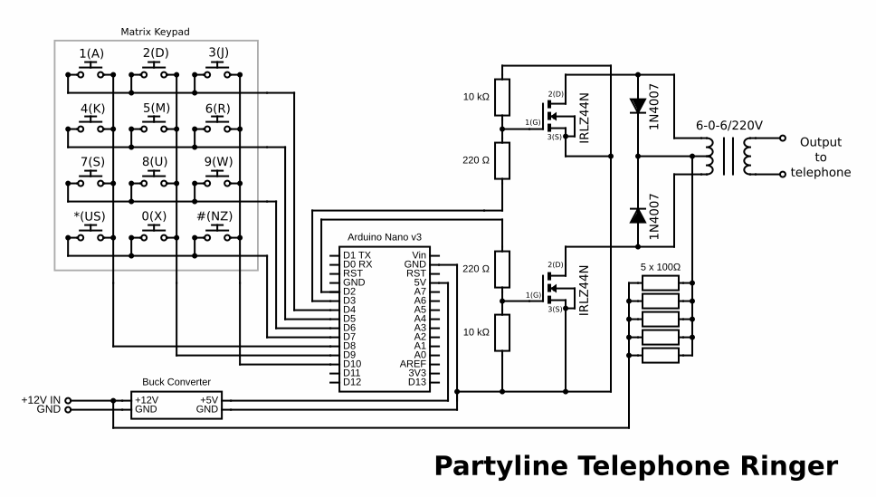
I decided to use an Arduino Nano to generate both the ringing cycles of 20Hz as well as the various ringing cadences. A 12 button keypad is used as an input to tell the Nano which cadence to ring. The 5V square wave pulses are then boosted to 12V using a pair of MOSFETs and further boosted to around 60V using a mains to 12V transformer in reverse.
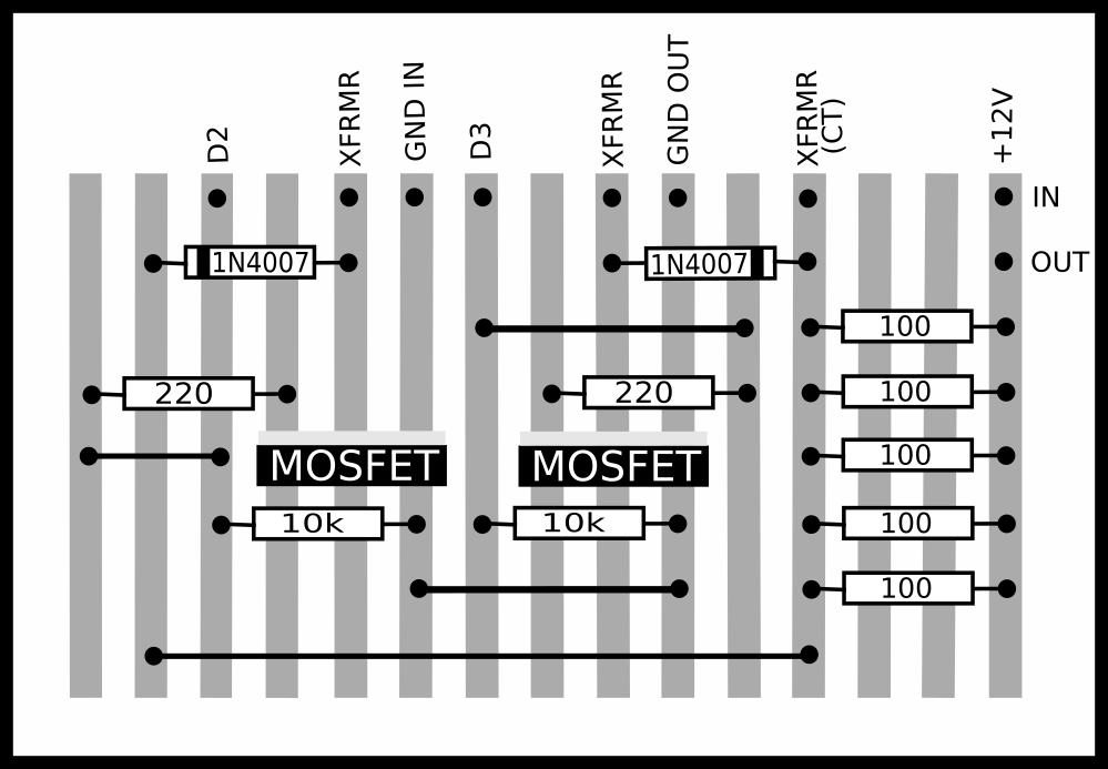
Things to take into account are that the telephone bells consist of two 500Ω coils in series, so at 60V this would draw up to 60mA, which amounts to 3.6W. The transformer is designed to work with an sine wave input of 230V, at 50Hz. Running it backwards with square waves at 20Hz will reduce its efficiency considerably. So, to be safe, I used a transformer rated at twice the required power, 7.2VA. And I decided to limit the input current by placing a 20Ω resistor in series with the 12V supply. This would limit the current to 600mA (if the transformer were treated as a short circuit). This would then result in 7.2W, the rating of the transformer. In order to ensure that the resistors don't get destroyed by overheating at this current, I used five 100Ω metal oxide resistors in parallel. In fact, the current is less than half of that, so we're well within the components' specifications.
Further to the transformer efficiency: with 230V in and 12.6V out, this is a ratio of around 18 to 1. I measured around 8VAC on the (now) input and around 40VAC on the output, giving a ratio of 5 to 1 - quite some difference! I don't know how accurate my multimeter is on square waves at 20HZ, but this is a good indication of what's happening.
The power supply is a 12VDC plug pack. The power to the Nano comes from a buck converter set to 5V.
BACKGROUND: PARTY LINESBecause of the huge distances involved, back in the days of landline telephones (or POTS, Plain Old Telephone Service), most of the rural areas around New Zealand would be served with a manual telephone service, and each telephone line consisting of one pair of wires, would have up to ten subscribers on it. In other words, up to ten homes sharing the same telephone number, except for the suffix of one letter. This meant that should someone wish to make a telephone call, they would first check that the line isn't being used by someone else, and then crank the handle of a magneto generator which would generate a ringing signal and ring all the other phones on the line as well as alert the operator at the telephone exchange.
To call someone else on the same line, you'd turn the handle in accordance to the Morse code of the letter suffix, e.g. for "U", two short rings followed by one long ring. To ring someone elsewhere, just turn the handle for one long ring. This would alert the operator who would then process your call and connect you.
For incoming calls, every time the phone rings you would take a note of the ringing pattern to see if it's yours before answering the call.
When a number of these manual exchanges (UMX - Unit Manual Exchange) were replaced with automatic ones (UAX - Unit Automatic Exchange), party lines were kept by installing "R" Units. (Each "Unit" was a rack of equipment serving a specific number of subscribers). The "R" Unit would convert one of the telephone number's digits to the Morse code ringing signal. So each home would have a slightly different phone number, but would still be across the same line and receive the ringing for everyone else on the line as well as their own.
The codes used were:
- 1 - A (short-long)
- 2 - D (long-short-short)
- 3 - J (short-long-long-long)
- 4 - K (long-short-long)
- 5 - M (long-long)
- 6 - R (short-long-short)
- 7 - S (short-short-short)
- 8 - U (short-short-long)
- 9 - W (short-long-long)
- 0 - X (long-short-short-long)
When the phones had to be converted to use the automatic service, they would have, in addition to the magneto generator, a push button switch and a rotary dial. To ring someone on the same line, you'd crack the handle according to the ringing code. To ring elsewhere, press the button and use the dial.
There are many improvements and changes that can be made to this project. I've left it the way it is because it works, and it's being used.
The power supply can be changed by removing the 12V-5V buck converter, and by feeding the 12V directly into the Nano board at VIN. The circuit also worked using bipolar junction transistors (BJT), as the currents are well within most of their capabilities. The 20 Ohm series resistor(s) in the 12V supply to the centre-tap of the transformer can be reduced/fine-tuned. The reason all of these are there is because I managed to destroy two Arduino boards during the development of this project. So I took all the precautions I could think of to ensure this wouldn't happen again. It turned out that the reason for their failures was the transformer: I started with one that was under-rated and developed short circuits, resulting in overloads and the destruction of a Uno and a Nano.
Another change possible is one I have only recently discovered: using a AG1171/AG1170/KS0835F module to create and supply the ringing, leaving the Nano to just look after the cadences. I have not tried this, but this looks promising as it would mean that there is no need for 12V, a transformer or the MOSFETs.


Comments
Please log in or sign up to comment.