My plan is to build a lamp that can be adjusted to focus its light on a reading/working spot or to spread light around for ambient lighting.
LEDs are widely used these days to provide light in public places, workspaces or at home. Still, there are not many LED lamps which allow for users to adjust the light temperature (or color) or how/where this light is projected.
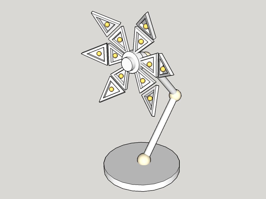
This project consists of a custom made lamp in the shape of a flower with six petals connected to a central hub. Each petal have two articulated parts and each half host a RGB LED.
Petals can change their angle relative to central hub and the tips of the petals can further change angle made with the root of the petal, this allowing the light produced by LEDs to be focused on a area or spread around.
The main roles of the Arduino 101 board are to control the motors or servos for petals position, to generate the PWM signals to control RGB LEDs and communicate with the user through bluetooth with the help of a mobile app or another bluetooth device.
With the help of the mobile app, user can control petals position, light color and intensity, create and store patterns for petals positions and LEDs working modes.
Commands can be given directly to lamp without a mobile app, with switches and potentiometers or by tapping the lamp base which hold Arduino board. These taps are detected with the help of Arduino's onboard accelerometer.
Being an Arduino powered device will have the possibility to be connected to a number of sensors like temperature sensor, PIR, RTC, humidity, etc and display their status in a visual way or react to parameters given by these sensors.
The buildAfter much thinking on how the lamp will look, I decided to try to build a lamp with a steampunk(ish) look.
This decision being made, I choose building materials as brass, brass beads, hinges, plywood, various nuts, bolts and wires, water based paint and various glues. On the electronics side, I used the kindly provided Genuino 101 and Grove Starter Kit for Arduino/Genuino101 plus four 10K potentiometers, a WS8212 RGB LEDs strip and 5 positions linear switch.
The petals were cut from 3mm pine plywood. The tip of the petal is attached with two hinges to the root of the petal which is also attached with a hinge to central hub.
After petals were completed I attached them to a central hub, a hexagonal piece made of plywood. This hub is attached to the mechanism which open or close petals.
Petals mechanismThe mechanism is based on a nut and bolt assembly, the bolt is coupled with the motor shaft and the nut assembly is connected to the petals command rods.
The stepper motor and controller used are the ones from Grove Starter Kit.
When the command rods are pulled towards motor, the petals lean forward closing the flower. When the command rods are pushed away from motor petals lean backward opening the flower.
To determine the position of the petals and the mechanism in order to avoid to damage the mechanics or the motor, I used a feedback potentiometer which is mechanically connected to the moving part of the mechanism. I determined by experiments the thresholds for open and close positions.
ElectronicsAs I wrote before, for this project I used the provided Genuino 101 and Grove Starter Kit for Arduino/Genuino101 plus four 10K potentiometers, a WS8212 RGB LEDs strip and 5 positions linear switch.
I wished to implement as many features as possible in this and I had in mind a number of parameters to control:
- petals position
- brightness
- light color
- independent control of LEDs R, G, B channels
- independent control of LCDs R, G, B channels
- bluetooth connection
- different LEDs/colors patterns
I wanted to control many of these parameters with potentiometers, looks more intuitive to me, but Arduino have a small number (6) of analog inputs. One way was to multiplex a number of potentiometers on one analogic input or to group the actions/pots and select the group I want.
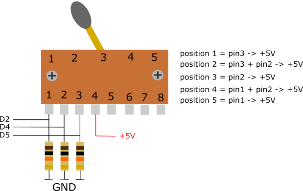
I choose the latter and I used a 5 way switch to choose between groups/ modes:
Position 1 - Mode 1 - potentiometers have these functions:
- pot1 - petals position
- pot2 - light intensity
- pot3 - light color, warm or cold light
Position 2 - Mode 2 - potentiometers have these functions:
- pot1 - change value for LEDs RED channel
- pot2 - change value for LEDs GREEN channel
- pot3 - change value for LEDs BLUE channel
This mode is used to tune the light color.
Position 3 - Mode 3 - potentiometers have these functions:
- pot1 - change RED channel for display background
- pot2 - change GREEN channel for display background
- pot3 - change BLUE channel for display background
This mode is to tune the background color of the LCD display.
Position 4 - select bluetooth control.
Position 5 - predefined combinations of LEDs/colors patterns.
To date, Mode 1, 2 and 3 are implemented.
Using this type of 5 way switch was a first to me. I wanted a linear not rotary multi pole switch and the only one I could find was a guitar switch.
I saw the middle pins connected together and I assumed that each lever position connect each of the pins to center. I was wrong... Each lever position trigger a combination of one, two or three pins if pins 4 and 5 are not bind together or up to five pins if pins 4 and 5 are bind. I choose to unbind them and in this way I got five positions using only three digital pins.
Unused digital and analog pins will be used for additional sensors and modules.
The lamp base is made from two identical plywood boxed mounted face to face and hold together with four screws mounted in corners.
The base box holds Genuino board + shield, potentiometers used to adjust lamp parameters, the 5 positions switch, voltage regulator and the Grove display.
The lamp pole is made from 10mm brass tube and hold the cables for motor and LEDs.
RGB LEDs are 36 pieces of 5V WS2812 leds, grouped three on each petal part. These LEDs are controlled with the help of Adafruit Neopixel library.
PowerAt the beginning, for test/programming purposes, I powered everything (Arduino + stepper + Leds) from the USB cable, but I was expecting when set the LEDs to higher brightness the current draw to be too high and the Arduino board reset, which was happened. When USB powered the voltage at 5V pin was around 4.8 - 4.9 Volts.
The obvious choice was to power the Arduino board from power jack, but to my surprise LEDs did not light up...
WS2812 LEDs are not just simple RGB LEDs, they have an integrated driver inside, powered at 5V, which control the Red, Green and Blue LEDs.
When my Arduino board is powered from power jack, the output of 5V pin is about 5.25V which seems fine for Arduino but is not tolerated by the WS LEDs...
So the next option was to use an external voltage regulator with an output voltage closer to 5V, to supply the required power to Arduino + stepper + Leds.
I choose for this task a 5V/5A step-down power regulator, D24V50F5 made by Pololu. 5 Amps might look overkill but 36 WS8212 ICs at about 60 mA/IC (20mA on each color) at full brightness result in 2160 mA current draw and I wanted to have some reserve for future use.
Besides, the output voltage of D24V50F5 is 4.95V which is fine for all devices involved. I sourced this voltage directly to 5V pin and so far everything looks good.
Finally, a couple of videos with Corolla in action. Watching them require some patience because the movement of the petals is quite slow.


_baVEVgguW1.jpg?auto=compress%2Cformat&w=48&h=48&fit=fill&bg=ffffff)


Comments