


Hardware components | ||||||
_ztBMuBhMHo.jpg?auto=compress%2Cformat&w=48&h=48&fit=fill&bg=ffffff) |
| × | 1 | |||
 |
| × | 1 | |||
 |
| × | 1 | |||
 |
| × | 3 | |||
 |
| × | 1 | |||
 |
| × | 1 | |||
Software apps and online services | ||||||
 |
| |||||
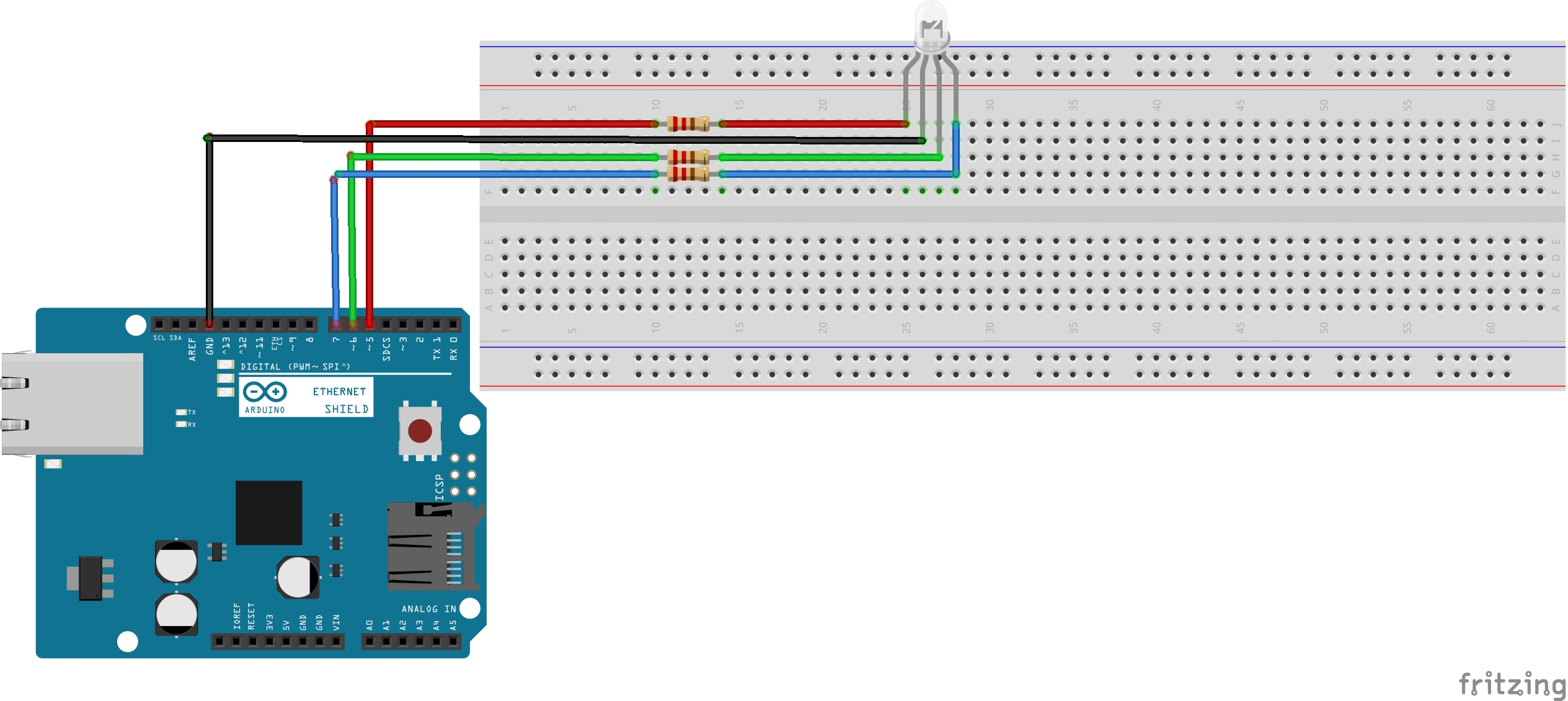
This project is made for Arduino beginners who are looking for learning how to interface the RGB led with the Arduino Uno. Also, we will understand the Common Anode (CA) and Common Cathode (CC) concept as well as the pulse width modulation (PWM) signals.
RGB LED Types and Structure
RGB LEDs have three LEDs inside them and usually, these three internal LEDs share either a common anode or a common cathode especially in a through-hole package. So basically, we can categorize RGB LEDs as either common anode or common cathode type just like in seven segment displays.
Common Anode
In a common anode RGB LED, the anode of the internal LEDs are all connected to the external anode lead. To control each color, you need to apply a LOW signal or ground to the red, green, and blue leads and connect the anode lead to the positive terminal of the power supply.
Common Cathode
In a common cathode RGB LED, the cathode of the internal LEDs are all connected to the external cathode lead. To control each color, you need to apply a HIGH signal or VCC to the red, green, and blue leads and connect the anode lead to the negative terminal of the power supply.
Basics of PWM (Pulse Width Modulation)
Pulse Width Modulation, or PWM, is a technique for getting analog results with digital means. Digital control is used to create a square wave, a signal switched between on and off. This on-off pattern can simulate voltages in between the full Vcc of the board (e.g., 5 V on UNO, 3.3 V on a MKR board) and off (0 Volts) by changing the portion of the time the signal spends on versus the time that the signal spends off. The duration of "on time" is called the pulse width. To get varying analog values, you change, or modulate, that pulse width. If you repeat this on-off pattern fast enough with an LED for example, the result is as if the signal is a steady voltage between 0 and Vcc controlling the brightness of the LED. In the graphic below, the green lines represent a regular time period. This duration or period is the inverse of the PWM frequency. In other words, with Arduino's PWM frequency at about 500Hz, the green lines would measure 2 milliseconds each.


Comments
Please log in or sign up to comment.