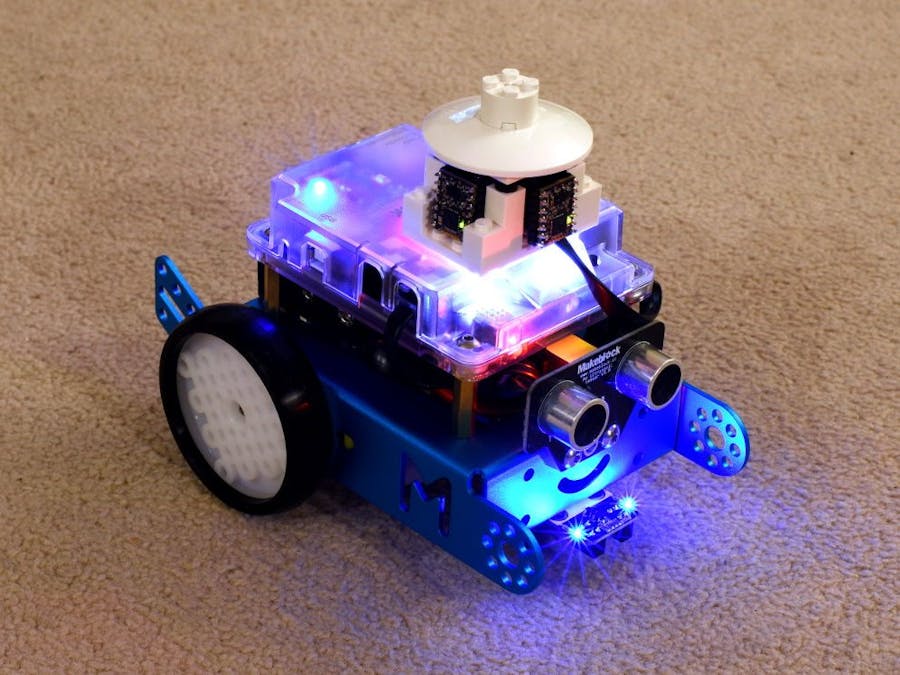
This guide will walk you through creating a simple connector for connecting four MappyDots to the Makeblock mBot robot. Connecting MappyDots will allow your mBot to accurately measure distances in 4 directions, which is a vast improvement over the included ultrasonic sensor.
First we are going to make the connectors to hook everything up. To do this, get the 8x 2.54mm (0.1inch) female headers and the RJ25 cable ready.
Snip one end off of the RJ25 cable to give you a length of about 20cm (8inch) and strip the individual wires out (if you are using the Me RJ25 breakout cable, you can skip creating this):
Note which is pin 1 of the RJ25 connector by looking at the colours inside the jack through the clear connector. Be aware that these colours can change depending on the manufacturer. Write the corresponding colours down for each pin for your reference.
Bend the pins of all the 2.54mm female headers at 45 degrees. Be gentle as they can break easily:
We are going to make a total of 4 right angle female to female connectors. To make each one, place one connector in a vice and the other along side it like so:
Now solder each pin. Use plenty of solder to make for a strong joint. Do this for the remaining 3 connectors.
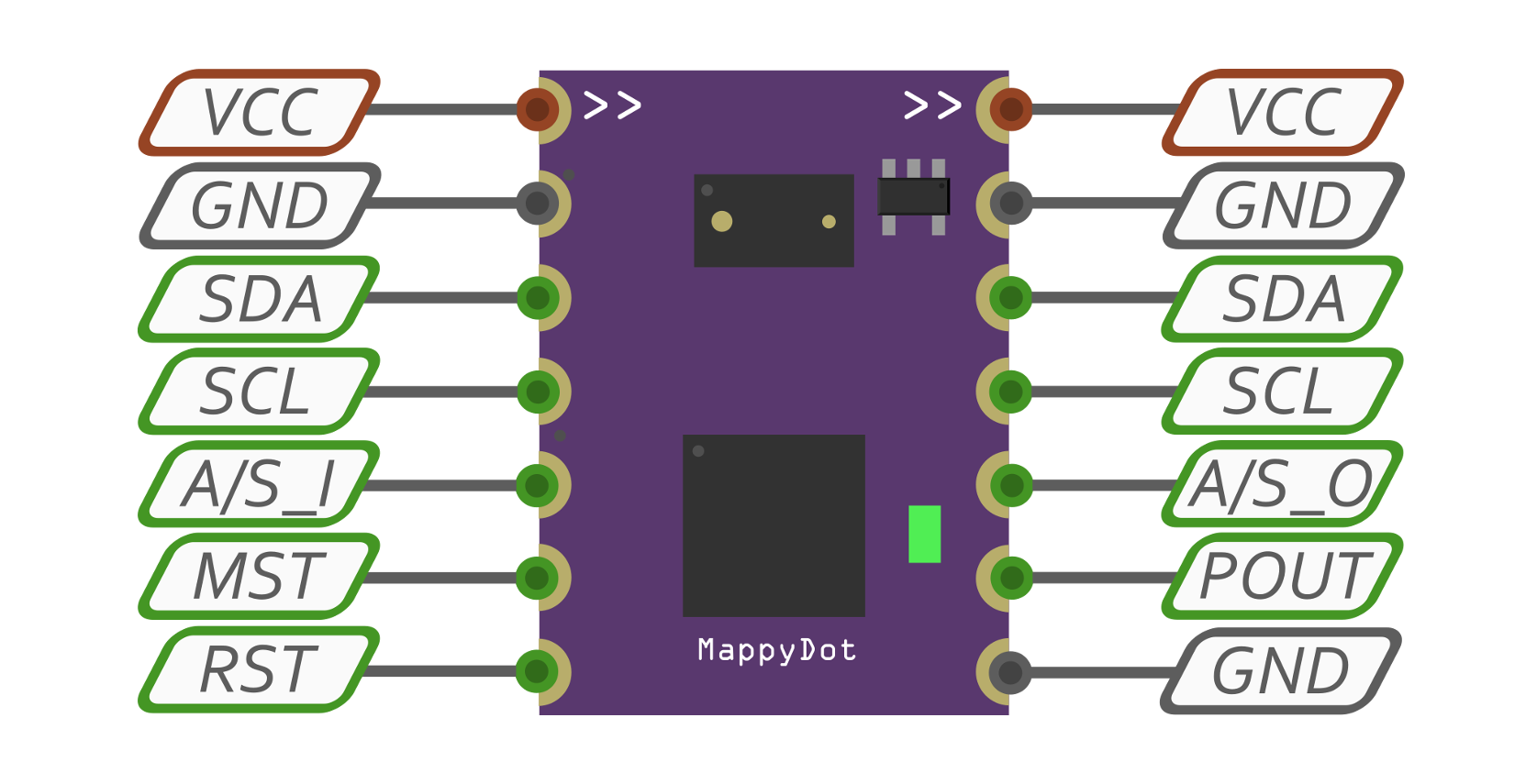
Grab your RJ25 cable with stripped wires and solder to one of the right angle connectors using pins 1 to 4 of the RJ45 cable. Pin 4 goes to the TOP of the right angle connector and pin 1 goes to the second from the bottom pin (see the attached schematics), leaving the bottom pin free like so:
If using the Me RJ25 breakout connector, take note of the pin names and connect them to their respective pin on the Me breakout, on one of the right angle connectors above. Your connectors are now ready.
To get things ready to connect, solder the 7pin 2.54mm male headers to each of the MappyDots' castellated pins. While we are only using 5 of these 7 pins, it is handy to have these extra two pins soldered on for future use.
Now you can connect everything up in a cross shape (as a ring with each MappyDot connected to the next one). Take note of the top of the top of the right angled connector with the RJ25 cable soldered on to it. The VCC (RJ25 Pin 4) pin should connect to the TOP of the MappyDot:
Once connected up, determine which MappyDot is going to be the front. On this side/MappyDot, place a solder bridge across the MST pads of this MappyDot. This MappyDot will be address 8.
You can now connect the RJ25 connector to a spare port on the mBot. Turn on the mBot and the MappyDots should now light up.
So how do we make a nice holder the MappyDots? We've opted for some Lego, as the mBot has a Lego holder on the top of the unit just for this purpose. Don't be afraid to get creative with how you place the MappyDots on top. However, be mindful of obstructing the view of the MappyDots.
Here's how we've done it:
This piece sits on top to hold it all together:
And putting the top on:
Now you can install the MappyDot extension from the GitHub repository into mBlock, and start creating code for the mBot, to run through mazes or avoid being kicked. If set up as above, the front sensor will be address 8 and the others sensors will have their addresses incremented anticlockwise while looking down from the top. There's an example sketch for you to play with on the repository:


Comments
Please log in or sign up to comment.