


Hardware components | ||||||
| × | 1 | ||||
| × | 1 | ||||
| × | 1 | ||||
| × | 1 | ||||
| × | 1 | ||||
| × | 1 | ||||
| × | 1 | ||||
Software apps and online services | ||||||
 |
| |||||
| ||||||
Hand tools and fabrication machines | ||||||
 |
| |||||
 |
| |||||
 |
| |||||
This project is part of a nationwide awareness campaign targeting rural communities that suffer from a lack of basic amenities. Limited resources leave villagers without reliable access to hospitals, fire stations, and even functioning police stations. Although police posts exist on paper, they rarely receive timely notifications and therefore cannot respond effectively.
My family descends from Morena, Madhya Pradesh. For routine checkups even, they used to travel 10 km were observed. In emergency situations, this distance can become life‑threatening, especially when panic makes it difficult to find help quickly.
Five years ago, on a visit home, I saw firsthand the stark contrast between city and village life. At the time, both technical and financial constraints made any solution seem out of reach. However, with my engineering background and community‑driven platforms like Hackster.io, I now believe we can bring essential services closer to these communities through a non‑profit initiative.
Together with a friend, we plan to create an alert system that will literally save lives by connecting villagers directly to nearby hospitals, fire services, and police stations. Our design uses a nRF54L15 based development board and four user‑friendly buttons. Each button triggers a distinct emergency message—medical, fire, police, or general assistance—transmitted via Ra02 LoRa modules interfaced over SPI. This low‑power, long‑range radio link works without cellular data or Wi‑Fi, overcoming the communication gaps in remote areas.
At the base station, a corresponding LoRa receiver will aggregate alerts and immediately forward them—via landline or internet—to the appropriate emergency service in the nearest city. By linking a cluster of villages to one hub, we can ensure that critical hours are not lost to distance or lack of awareness. While the technology itself is well‑established, its focused application here will make a profound impact on rural safety and well‑being.
The Ra-02 LoRa SX1278 module, developed by Ai-Thinker, is a compact and efficient wireless communication device designed for long-range, low-power applications.
It operates on the 433 MHz frequency band and utilizes Semtech's SX1278 transceiver chip, which employs LoRa™ spread spectrum modulation technology.
This technology enables the module to achieve high sensitivity (down to -148 dBm) and a communication range of up to 15 km in open environments, making it suitable for applications like remote monitoring, smart agriculture, and emergency alert systems.
The Ra-02 module's SPI interface facilitates easy integration with microcontrollers, allowing for efficient data transmission and reception. In summary, the Ra-02 LoRa SX1278 module offers a reliable and efficient solution for long-range wireless communication needs, combining high performance with low power consumption in a compact form factor which makes it suitable for our application.
The system is built around the Ra-02 SX1278 module to establish wireless communication in areas with no access to cellular or Wi-Fi networks. SPI is used as the communication protocol for its simplicity, speed, and reliability. It allows direct interfacing between microcontrollers and the LoRa module with minimal overhead, keeping the setup efficient and adaptable for low-power, long-range operations.
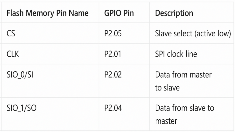
Nordic nRF54L15 DK and Ra-02Sx-1278 Connection
The nRF54L15 DK features four SPIM instances (SPIM0–SPIM3) with EasyDMA, enabling direct memory‑to‑peripheral transfers without CPU overhead; SPIM2 and SPIM3 are designated for high‑throughput use—supporting clock rates up to 32 MHz—for external peripherals such as LoRa radios, displays, or flash memory, as highlighted in Nordic Developer Academy’s nRF Connect SDK. Each SPIM channel has remappable SCK, MOSI, MISO, and CS pins via PSEL registers and signals transfer completion through EVENTS_END, allowing interrupt‑driven or PPI‑triggered workflows. Proper shutdown of SPIM after transfers reduces standby current and preserves battery life in remote deployments
To establish spi using the nRF54L15 DK, certain solder traces have to be removed out as mentioned in the documentation.
After removing the traces, we are ready to interface nRF54L15 DK and Ra-02Sx-1278.
The flow of data should look similar to:
*at the receiving end, an indicator will be connected to get the information of the requesting village.
Arduino and Ra-02Sx-1278 (Previous Project)
A similar setup was validated on an Arduino Nano, mapped to the Ra‑02 Sx-1278 here. This prototype confirmed end‑to‑end packet delivery, timing, and basic range in our target environment, proving the concept’s viability.
For production, the nRF54L15 DK is a superior choice. Its on‑board 2.4 GHz radio and Cortex‑M4F core offer higher processing power and memory for complex packet handling. EasyDMA‑driven SPIM reduces CPU load during SPI transfers, while built‑in GPIOTE/PPI enables hardware‑level interrupt response for LoRa’s DIO0 events. The nRF’s low‑power modes, richer GPIO set, and integrated debugger streamline development and extend battery life—critical for remote, maintenance‑free deployments.
Components Used- nRF54L15 DK- Main microcontroller
- Ra-02 SX1278- Long-range wireless transmission
- Push Buttons- Trigger alerts
- Power Supply- Battery/solar setup for rural use
- Base Station LoRa- Central node for receiving and routing
NPM1300 funtion and features
- Dual high-efficiency buck regulators (up to 400 mA each)
- Dual load switches with adjustable slew rate
- Integrated Li-ion/Li-Po battery charger with programmable current
- Battery voltage and temperature monitoring, fuel gauging
- Ship mode for ultra-low battery drain
- Power-on reset and system reset controller
- Up to 6 configurable GPIOs for wake-up/interrupts
- Watchdog timer, brownout detector
- Programmable start-up sequencing
- I2C interface with optional second address
- Overcurrent, thermal shutdown, battery short-circuit, and input overvoltage protection
Set up
Open nRF Connect application and install NPM power up
Then Launch it
Then, you need to select which NPM — either the NPM2100 or NPM1300 — is used in your circuit. In the nRF54L15, the NPM1300 is used, so I selected NPM1300Software Implementation
Then, connect the battery and the USB VBUS power supply to the solar input. In my case, I am using a 5-volt adapter to simulate the solar input.
Here, you can see the regulator options and the configuration settings for mode control in Buck 1 and Buck 2. You can manually force PFM or PWM mode, or configure mode control via a GPIO
Here, we can output the ADC values, such as voltage, current (indicating whether the battery is discharging or charging), the temperature of the NTC, and the state of charge
1. GUI Based- Development Environment SetupInstall nRF Connect for Desktop and the J-Link Installation. In VS Code, add the nRF Connect Extension to manage projects and debug sessions.
Officially supported for NCS ≥ 2.0.0; offers project wizards, device‑tree syntax checking, and Kconfig autocomplete.
Free for use with nRF 5 SDK up to NCS 1.9.x but deprecated in favor of VS Code for NCS ≥ 2.0.0.
- Open nRF Connect, install the toolchain and sdk sample for your board.
Use the latest stable NCS release (e.g. v2.9.x) to ensure compatibility with nRF 54 series boards
- Open nRF Connect, select the “Application” sample for your board.
- Code and then Configure your project settings (board, build directory, LoRa parameters).
- Build and Flash directly through the GUI buttons—the integrated J‑Link will program the DK.
- 4 gpio buttons correspond to each of the emergency station and based on that data will be sent through Ra-02 Sx-1278.
- Install West, Zephyr SDK, and GNU Arm toolchain; set
ZEPHYR_BASE.
- Build the app:
west build -b nrf54l15dk path/to/app- Flash via J‑Link:
west flash


Comments
Please log in or sign up to comment.