

Hardware components | ||||||
 |
| × | 1 | |||
 |
| × | 1 | |||
 |
| × | 1 | |||
Software apps and online services | ||||||
 |
| |||||
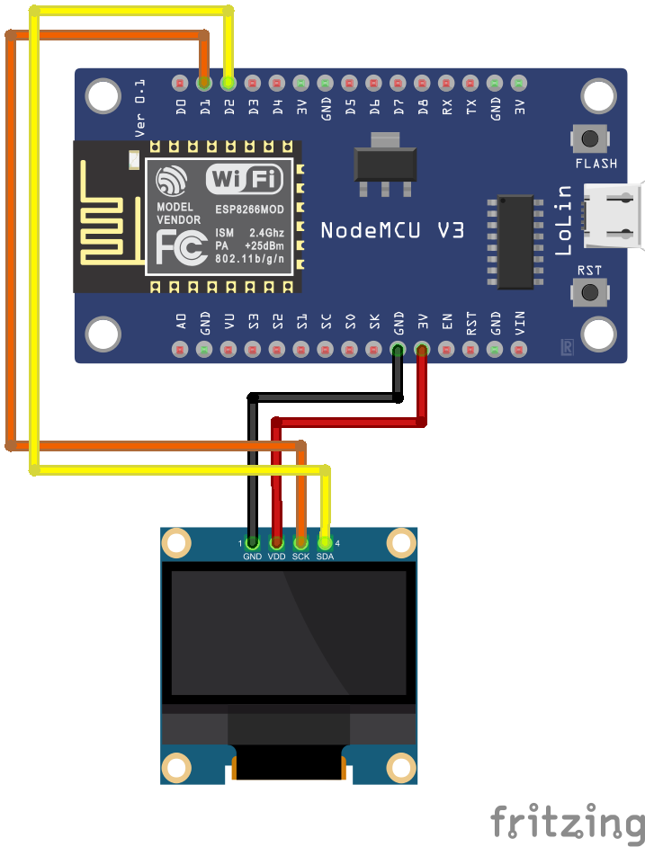
This is my first project where I have used an OLED display module and the first idea that came to my mind was making an OLED clock. I am fascinated by OLED technology as it is compact, consumes less power, does not require a backlight and can display deep black levels compared to LCD. Moreover, there are several functions provided by the Adafruit Library that provides simplicity while making OLED related projects. In this project, the OLED display provides date, day and time in digital and analog clock style.
Since the the NodeMCU has a built-in ESP8266 WiFi module, I decided to make use of NTP server to obtain accurate time instead of using an additional RTC module. As an advantage, the user need not set the time manually as the NodeMCU is synchronized to the NTP Server provided it has internet access via WiFi.
Network Time Protocol(NTP)-NTP is a standard Internet protocol(IP) that is used to synchronize computer clock connected to the network.
In my program I have specified the address of the NTP server as "asia.pool.ntp.org" that returns asia sub-zone time. The time I received from NTP server was 5:30 hrs slow from from the time in my country i.e India, so I had to set my offset time(in the code) as 19800( 5hrs 30 mins = 19800 seconds) to obtain the correct time.
I have used trignometric concepts on making the Analog style clock.
The basic logic is to calculate the angle to be moved by the hand( hour, minute and second) of the clock depending upon the time and using sine and cosine functions of the angle to obtain the displaced x, y coordinates. Plotting a line between the center coordinates and the displaced x, y coordinates can provide a correct hand movement of the clock.
We know that the second hand moves 360 degree for every 60 seconds. So for 1 second, the second hand moves 360/60=6 degrees. Similarly, the minute hand moves 360/60mins=6 deg for every minute and the hour hand moves 360/12hrs= 30 degrees for every hour. The center coordinates and the radius of the clock circle is fixed. From the fig below, Using sine and cosine functions we can obtain the displaced x and y coordinates of the clock.
In this example, consider the Second hand is at 30 degrees in the 1st quadrant. Thus, the number of seconds elapsed is 30/6 = 5 seconds ie: the second hand points to hour hand 1. To find the displacement in the x coordinate, we will need to calculate the length of AB that is r*Sin(30). Similarly, for y coordinate displacement, we will need to calculate the length of OB that is r*Cos(30) where 'r' is the radius of the circle.
Using the center coordinates and the displacement coordinates, a line can be plotted indicating Second hand using the Adafruit GFX library function
void drawLine(x_center,y_center,x_center + r*sin(angle),y_center - r*cos(angle), color);
in the 1st quadrant, as the clock moves from 0 to 90 degrees(ie from 0 to 15 seconds), the x coordinate should keep increasing and the y coordinate should keep decreasing. Thats why I have used + r*sin(angle) and - r*cos(angle).
Since the IDE uses radians to calculate trignometric Sine and Cosine(see here), I have multiplied the angle with 0.0174533 (as 1 deg= 0.0174533 rad) to convert it to radians which will give a result between -1 and 1.
Although I believed this syntax would work only for 1st quadrant, I have noticed a full clockwise rotation when I tried it with other quadrants too(with no sign change in displacement coordinates). The change in sign of Sine and Cosine in different quadrants could be the factor (will need to figure it out).
The same concept has been used to indicate the minute and hour hand too.
Uploading the CodeThe code requires the following libraries to be installed on the IDE-
1. NTPClient by Fabrice Weinberg.
2. Adafruit SSD1306 by Adafruit.
3. Adafruit GFX Library by Adafruit.
Make sure to enter the SSID and Password of your WiFi router on the source code before uploading it to the NodeMCU.
Here is the final demo of the project.


Comments