

Hardware components | ||||||
_ztBMuBhMHo.jpg?auto=compress%2Cformat&w=48&h=48&fit=fill&bg=ffffff) |
| × | 1 | |||
 |
| × | 1 | |||
| × | 2 | ||||
 |
| × | 1 | |||
 |
| × | 1 | |||
 |
| × | 1 | |||
Software apps and online services | ||||||
 |
| |||||
| ||||||
| ||||||
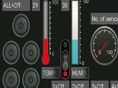
This project is based on an Arduino Uno. In this project, we perform the following operations using an Android device and an Arduino:
1) Control all the appliances via Android app through HC-05 Bluetooth module.
2) Turn all the room appliances off, when everyone leaves the room.
3) Read the temperature and humidity percentage of the room.
4) Count the number of people in the room. (Any other function, such as opening of door automatically, can be implemented instead.)
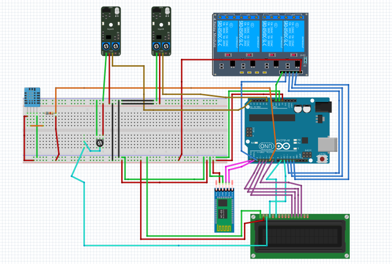
Hardware Connectionsa) Bluetooth ConnectionØ The Vcc and Gnd of the module goes to Vcc and Gnd of Arduino.
Ø The TXD pin goes to RXD pin of Arduino and RXD pin goes to TXD pin of Arduino i.e (digital pin 0 and 1), for obtaining communication in b/w Bluetooth and board.
Pin Connections: As shown above
b) IR Proximity SensorØ IR transmitter emits infrared light and another receiver (usually photo-transistor) receives that IR light after reflection.
Ø The module has both analog and digital output:
Analog output can be used to calculate the distance to the nearest object while
digital sensor can be used to trigger an action when the module detects an obstacle.
Analog pin read the distance to the nearest obstacle and outputs analog values.
The digital output can be connected to trigger an activity when the distance becomes below a threshold value.
The threshold value of distance can be controlled by adjusting the pot(Knob like structure (it’s a variable resistance).
Now in order to use proximity sensors to initiate any task as the person enters the room, we have to place the proximity sensors as such they can track the interruptions occurred due to entering of the person.Here two IR sensors are used.
By using this we can initiate any task such as Turn on of any room light, counting number of persons entered, opening and closing of gate automatically, turn off all the lights if no one is in the room(for this we can also install a PIR sensor), etc.
Here we only show the initiation of a counter using proximity sensors.
Pin Definition
· AO: This is the analog output pin from the sensor and should be connected to Analog input pin of microcontroller. If you are using an Arduino, this can be connected to any of the analog pins A0 through A5 (on UNO for example). Analog output from IR proximity sensor can be used to identify distance to the nearest obstacle (note that it varies with change in color of different materials).
· DO: The pin is connected to a pull-up resistor and will read high. You can adjust the pot to set a threshold value. When it crosses the threshold, the pin goes low and signal LED turns on. This setup is very useful when you need to trigger an action when certain threshold is reached.
· VCC: Positive power pin and this should be connected to VCC (or +5V) of your microcontroller.
· GND: Ground pin and this should be connected to GND(or 0V) of your microcontroller.
Pin Connection: [Vcc and Gnd must be taken from the board, you can use the same Vcc and gnd to supply other components using parallel connections.][(IR sensor 1) DO => pin 14;( IR sensor 2) DO => pin 19]
c) DHT11 SensorThis is a sensor used to sense temperature and humidity. This sensor includes a resistive-type humidity measurement component and an non linear resistance (NTC) temperature measurement component.
When the connecting cable is shorter than 20 metres, a 5K pull-up resistor is recommended (otherwise the results may not be obtained); when the connecting cable is longer than 20 metres, choose a appropriate pull-up resistor as needed.
Power and Pin
DHT11’s power supply is 3-5.5V DC. When power is supplied to the sensor, do not send any instruction to the sensor in within one second in order to pass the unstable status. A capacitor of sufficient value can be added between VDD and GND for power filtering.
Pin Connection:- [VDD and GND msut be given as shown above in fig 4][ VDD(with 5k resistor)=> pin 6]
d) LCD Interfacing with the Arduino ModulePin diagram and description of each pin have explained in the following table.
Pins Connection: [rs =>pin 10, en =>pin 9, d4 =>pin 5, d5 =>pin 4, d6 =>pin 3, d7 =>pin 7;]
LCD is used to display current temperature, humidity, etc.
e) Relay BoardHere I used a quad-channel relay board, which is a simple and convenient way to interface four relays for switching application.
Features:
Input supply 12 VDC @ 170 mA
Output four SPDT relay
Relay specification 5 A @ 230 VAC
Trigger level 2 ~ 5 VDC
Berg pins for connecting power and trigger voltage
LED on each channel indicates relay status
Power Battery Terminal (PBT) for easy relay output and aux power connection
Four mounting holes of 3.2 mm each
PCB dimensions 88 mm x 68 mm
Applications: Industrial controls, microwaves oven, fans, DC motor, AC lamp, solenoid remote controls, etc.
Relay Load (Contact Capacity of Relay)
7 A @ 230-250 VAC
10 A @ 120 VAC
10 A @ 24 VDC
CN1 – CN4 Connector : Relay 1 to 4 (S1 to S4) Output (Normally Open/Normally Close)
CN5 Connector : Control Signal Input, Trigger 2 to 5 VDC and Supply Input 12 VDC
D2, D4, D6, D8 : Relay On/Off LED Indication
CN6 Connector : Axillary Supply 12 VDC
Pins connections:[D2=>pin2; D3 => pin13; D4 => 12; D5 =>pin 11;VCC and VDD are connected to remaining VCC and Gnd pins of board or by taking supply and gnd from connections]
PIN Connections:


Comments