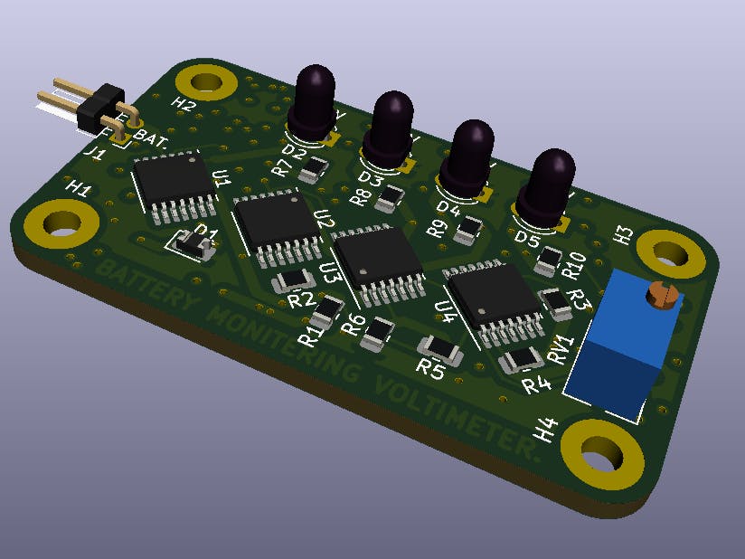
The system has the main purpose of working as an indicator to the drivers of the vehicles on the battery life. It will indicate the voltages in the battery at a particular moment with an interval of 11V, 12V, 13V, and 14V. Although a voltmeter can be bought off-shelves, it is quite cheaper and interesting to build your circuit so that you can have the arrangement of the components in a compact manner and the way you would appreciate it. For the newbie, a voltmeter is an electronic or electromechanical device that is used to measure the potential difference between two given points of an AC or a DC source. In our system, the voltage will be measured by incorporating the voltmeter with the amount of charge that is available in the car battery.
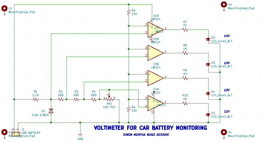
How the system worksFrom the schematic, the voltmeter terminals are connected across the battery terminals. In other words, the battery terminals are connected to the inverting ends of the LM324 IC. In the system, we shall have the indicated and the reference voltage. Our indicated voltage is what we get from the voltmeter display while the reference voltage is what we obtain from the Zener diode D1. The indicated voltage is compared with the reference voltage. The Zener diode will allow current in one direction just like any other diode but if the breakdown voltage is exceeded, it allows current to flow in the opposite direction too.
The potentiometer resistor of about 10K is connected to help in the changing of the voltage levels in terms of the Light-emitting diodes glowing. The LED indicators show the car battery voltage level in intervals of 1V which is 11V, 12V, 13V, and 14V.
Components and specificationsU1A, U2A, U3A, and U4A - LM324 1CsR1 - 1.2K resistor
R2, R3, R4 - 680 Ohms ResistorsRV1 - 10K potentiometer
R5 - 15K resistorR6 - 10K Resistor
R7, R8, R9, R10 - 1K ResistorsD1 - 5.6V Zener diode
D2, D3, D4, D5 - Light-emitting diodesSuch boards can be ordered for fabrication through PCBway. KiCAD has made it easy for users to order such boards by introducing the PCBway plug-in for Kicad. It is an easy-to-do process.
Open your latest version of KiCAD. Click on 'Plug-in and the content manager' shown in the screenshot below.
On the pop-up window, scroll down until you get to 'PCBway plug-in for Kicad' then hit install to do the installation of the plug-in and that is all you are ready to go.
The plug-in will help you share the Gerber files, drill files, BOM files, pick and place files, and any other necessary design output to PCBway for manufacturing with just one click.


_4YUDWziWQ8.png?auto=compress%2Cformat&w=48&h=48&fit=fill&bg=ffffff)


_Ujn5WoVOOu.png?auto=compress%2Cformat&w=40&h=40&fit=fillmax&bg=fff&dpr=2)


Comments