


Hardware components | ||||||
_ztBMuBhMHo.jpg?auto=compress%2Cformat&w=48&h=48&fit=fill&bg=ffffff) |
| × | 1 | |||
 |
| × | 1 | |||
| × | 1 | ||||
Software apps and online services | ||||||
 |
| |||||
 |
| |||||
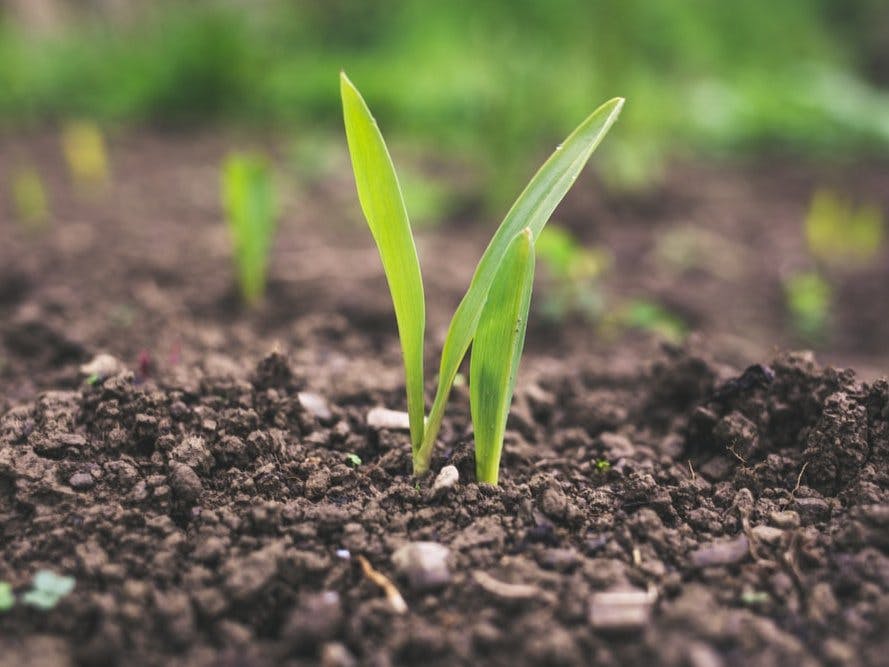
More and more it has become necessary to use technologies in the field, not to use soil management for crops, not to use water for irrigation and human management indispensable for modern agriculture.
An example of a technique is the use of sensors for IoT and actuators that make everything in the field more efficient and modern, have you ever thought about seeing what is happening in the field, seeing the state of a plant, knowing when to replace water, and when the lack of water, with a modern graphic interface that is already possible.
In this article, we will take the first step towards developing an intelligent system aimed at monitoring and controlling soil moisture in plants and plantations.
We will start by learning how to use the soil moisture sensor, also called a hygrometer, together with an esp8266 Nodemcu 1.0, showing data in variables on the Ubidots IoT platform.
Project Development MethodologyFrom now on we will proceed with our hardware assembly, the circuit and step by step on the Ubidots platform to view our data on it.
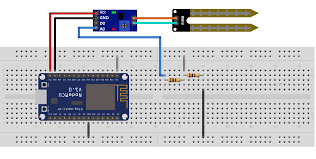
List of components and schematic of the electronic circuit
The complete circuit will use the following components:
- NodeMCU 1.0 (módulo ESP12E)
- Protoboard
- Soil moisture sensor hygrometer
- Jumpers
- Resistor 1k 1/4W
- Resistor 2k 1/4W
From the components above, we developed the following circuit:
Hereafter, we'll explain how to configure the Arduino IDE to monitor the sensor values.
After testing this circuit, was created the printed circuit board as is shown in the next section.
Printed Circuit Board - PCBGOGOFirstly, was developed the electronic schematic circuit. In the circuit was used the NODEMCU Board and a header pin male to connect the moisture sensor for IoT.
In addition, was used a voltage divider electronic circuit to offer the voltage signal between 0V and 1V in the analog pin of the NODEMCU Board with the moisture sensor for IoT. This circuit was used because the sensor offers the voltage signal between 0V and 5V.
In Figure 2 is presented the Electronic Schematic developed with PCBGOGO.
From this schematic, was produced the PCB Design Layout presented in Figure 3.
From this developed PCB Design Layout, is presented the 3D PCB Layout in Figure 4.
From the project, the project was developed and the system was integrated with NODEMCU and Ubidots. The process will be presented in the next topics.
Configuring the Arduino IDEIn order to work with the NodeMCU ESP8266 platform on the Arduino IDE, you will need to install the ESP8266 platform using the preconfigured Arduino Board Manager. If you are not familiar with adding a board with the Arduino IDE
https://help.ubidots.com/articles/2033398-setting-up-the-arduino-ide-for-ubidots.
With the esp8266 platform installed, select the esp8266 device you are working with. In this case, we are working with a “NodeMCU 1.0 (module ESP12E)”.
To select your board from the Arduino IDE, select Tools> Board “NodeMCU 1.0 (module ESP12E)”. Download and install UbidotsMicroESP8266.
For a detailed explanation of how to install libraries using the Arduino IDE.
https://help.ubidots.com/articles/2033398-setting-up-the-arduino-ide-for-ubidots.
The library will create a new Ubidots device called "ESP8266" receiving the ESP8266 MAC address as the unique device label.
Now, we'll see the source code of this project.
Source code of ProjectThe source code of the assembly can be seen below. See carefully the TOKEN settings "your_token_here" (here you must define your token acquired on the Ubidots platform), WIFISSID"name of the wifi network" (here is determined by the name of your router's wifi network), PASSWORD"password of the wifi network" (this is determined by your router's password).
Change these parameters for your WIFI network login and password.
#include "UbidotsMicroESP8266.h"
#define TOKEN "seu token aqui" // Ubidots TOKEN
#define WIFISSID "nome da rede wifi" // Wi-Fi SSID
#define PASSWORD "senha da rede wifi" // WIFI Password

Ubidots client(TOKEN);

void setup()
{
Serial.begin(115200);
client.wifiConnection(WIFISSID, PASSWORD);
}

void loop()
{
amostra_umid = analogRead(0);
//We will use the map function to map the values read on the analog input range from 0 to 1023, and will be remapped to another range from 0 to 100%.

float value1 = map ( amostra_umid, 0, 1023, 0, 100 );

client.add("Umidade", value1);
client.sendAll(true);

delay(5000);
}
Now, we'll explain how to develop the dashboard control in the Ubidots Platform to receive the data of the moisture sensor for IoT.
Project Development on the Ubidots PlatformAfter assembling the circuit and writing the code, we must send the data to the Ubidots IoT Platform. This electronic circuit will send data through the Nodemcu board using the WIFI network to any device connected to the internet.
First, we will present how to obtain the TOKEN of the platform, to use in our code. Click on the user symbol and then click on the API Credentials option.
The result is shown in the figure below.
Next, we will see what it shows on the red arrow, we copy our token and use it in our code presented above. Ready here we take the first step.
When we transfer our firmware for NODEMCU Board, we can open the platform and we will see a device created automatically by NODEMCU Board on the platform. See Figure 4 presented below.
From here we will create our smart panel, added widgets, as we see the arrow when clicking we will see the options to choose the indicators and graphics.
In our case, we chose an indicator to see our data.
Finally, as we can see in the image below, we chose a tank-type widget to show the dynamics of our moisture.
Right after that, we must choose the device created by NODEMCU connected with WIFI network.
Here it is important to pay attention to the choice of our created variable, in our case "Humidity". Finally, we must define the minimum and maximum values for our widgets.
To remember that we defined the remapping of the beautiful data on the analog port in the map function seen in our code. We set the minimum value for 0% and the maximum value for 100%.
Ready! Our dashboard is created and we can see the data arriving on your dashboard. Dynamically as the soil moisture increases or decreases, the sensor shows on our panel.
Finally, we'll learn how to integrate the telegram alert event in the Ubidots Platform.
How does the integration of an event with Ubidots work?
We will see a very interesting part of the Ubidots platform, called “Events”, if we click on this option in the menu part on the platform located above we will have the following step by step:
First, we need to choose the device for which the event will be created:
Second, we must add a new event. Then we need to choose the variable for the event. In our case is the “Humidity” variable as shown in the image below:
In the third step, we will need to create a small logic in the fields inside the red circle to be the trigger for our event, which will be sending a telegram to our telegram account.
We chose to define whether the humidity variable is below 10% sends a telegram to our cell phone.
After that, we must define the number and the message that we want to receive your cell phone.
Finally, our event is configured and when occurring the specific event the user will receive a message with alert in your cell phone.
The result is presented in Figure 15 below.
Now, let your system update or monitor the soil capture and wait to receive a message on your cell phone. This way, you will be notified when your plant needs water to keep it alive in the garden.
ConclusionIn variable monitoring systems, it is essential to implement event-based alerts. Through the events, we can know when a measured variable has exceeded a certain programmed value.
In addition, it allows us to leave the system operating automatically and act based on events.
Therefore, if you are interested in monitoring a quantity and need to be alerted, use the events of the Ubidots platform and connect your devices on the internet. That way, you will have a secure application and will always be notified when any scheduled event occurs.


Comments
Please log in or sign up to comment.