

Hardware components | ||||||
 |
| × | 1 | |||
 |
| × | 1 | |||
 |
| × | 1 | |||
Software apps and online services | ||||||
 |
| |||||
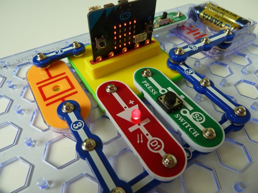
The snap:bit is an electronic component for the Snap Circuits educational electronic kit. It features a socket for connecting the BBC micro:bit. This allows the Snap Circuits to be programmatically controlled by the micro:bit.
This project demonstrates how to program several components of Snap Circuits with the BBC micro:bit.
This project builds on top of what we learned in the Connect LED, the Connect Press Switch, and the Connect Whistle Chip projects.
We will program the BBC micro:bit to display a timer that increments by pressing the Press Switch (S2) of Snap Circuits. Pressing button A on the micro:bit starts the countdown of the timer. Each second it will light the LED (D1) and play a sound on the Whistle Chip (WC).
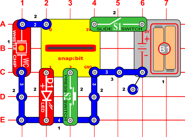
Snap Circuits diagramBuild the circuit shown in the diagram above.
CodeYou can build the code yourself in the MakeCode Editor. You will find the "digital write pin" block under the Advanced > Pins section.
Alternatively, open the ready project here: https://makecode.microbit.org/_Kxbcya4RyRm1
Once ready, download the code to your micro:bit. Then disconnect all cables from your micro:bit. Both the USB and the battery pack must be disconnected from the micro:bit.
How it works...When you close the slide switch (S1), the Battery Holder (B1) powers the snap:bit through the 3V snap and the micro:bit turns on. The “on start” event triggers, which sets the “count” variable to 0 and displays it on the micro:bit.
Press the press switch (S2) and release it within 1 second. This closes the circuit between the P2 and GND pins of the micro:bit. The “on pin P2 pressed” event triggers, which increments the “count” variable by 1 and updates the display of the micro:bit with the new value. Press the switch as many times as you wish and watch how the counter increments.
Now press the A button on the micro:bit. The “on button A pressed” event triggers and the micro:bit starts the countdown loop. The loop iterates as many times as the value of the “count” variable.
In each iteration, the micro:bit writes a digital 1 signal to pin P1. This closes the circuit between the P1 and GND pins and the LED (D1) turns on. Then the micro:bit plays a sound. Afterward, it writes a digital 0 to pin P1 to open the circuit between the P1 and GND pins to turn the LED (D1) off. Then the micro:bit pauses for 1 second, decreases the value of the “count” variable by 1, and updates the display with the new value.
This way we see the micro:bit counting down the remaining time while playing a sound and lighting the LED every second.
Finally, when the value of the “count” variable is down to 0, the loop ends and the micro:bit plays the “dadadum” melody. The LED (D1) is on while the music is played.
Another variantLet's experiment a bit with this project. How about disconnecting the LED (D1) from pin P1, and connecting to pin P0 right over the Whistle Chip (WC)? Like on this picture:
What would happen if you run through the project once again? Let's see:
Now, the LED (D1) is even better in sync with the sounds played through the Whistle Chip. It even flashes in rhythm with the "dadadum" sound played at the end.
How is that possible?
The micro:bit plays sounds by writing an analog signal to pin P0. Components like the Whistle Chip and the Speaker can convert this analog signal into sound.
By connecting the LED (D1) right over the Whistle Chip (WC), we made the both connected in parallel to pin P0. This means that both components receive the same current from pin P0.
In the Adjust LED Brightness and Pulsing LED projects we learned that we can light the LED with different brightness by using exactly an analog output to the micro:bit pins. So the analog signal generated by the micro:bit through pin P0 to play the sound can be also used to light the LED.
And this is how the LED (D1) responds to the playing sounds by the micro:bit.


Comments
Please log in or sign up to comment.