

Hardware components | ||||||
_ztBMuBhMHo.jpg?auto=compress%2Cformat&w=48&h=48&fit=fill&bg=ffffff) |
| × | 1 | |||
| × | 1 | ||||
 |
| × | 1 | |||
 |
| × | 1 | |||
 |
| × | 1 | |||
 |
| × | 1 | |||
 |
| × | 1 | |||
 |
| × | 1 | |||
| × | 1 | ||||
| × | 1 | ||||
We've created a way for you to connect and configure Bluetooth control of a lamp or any AC-powered device in your home using an Arduino as the brain. Let's get started!
1. Blink an LEDBlinking an LED is the “Hello, World” of hardware — an easy test to ensure that your Arduino is set up correctly. Grab your Arduino board, a breadboard, an LED, a 220Ω resistor, and some jumper wires, and follow Massimo Banzi’s tutorial. The example code will set the Arduino’s pin 13 as HIGH for 1 second (switching the LED on) and then LOW for 1 second (off), and so on.
2. Add a pushbutton switchNow connect the little tactile pushbutton and a 10kΩ resistor as shown in Figure A.
Download this project’s Arduino code. In the Arduino IDE, open the Library Manager and type BLEPeripheral into the search window, then select the library BLEPeripheral.h and click Install.
Next open the sketch ble-smart-switch.ino in the Arduino IDE, and upload it to your Arduino. Now your LED should turn on when you push the button, and off when you push the button again.
Now that you have a working pushbutton light switch, let’s add Bluetooth LE. The Bluetooth board we’re using is the Adafruit Bluefruit LE board based around the Nordic Semiconductor nRF8001 chipset. Wire the board to the Arduino as shown in Figure B, using pin 2 for RDY and pins 9 and 10 for RST and REQ, respectively.
S
Open the Arduino sketch ble-light-with-powertail.ino and read along with the comments to see how your Smart Light Switch code will establish the service:
» Create a peripheral instance using the BLEPeripheral library. » Create a lightswitch service with UUID of 0×FF10. » Create the Switch and State characteristics and descriptors.
BLEPeripheral blePeripheral = BLEPeripheral (BLE_REQ, BLE_RDY, BLE_RST); BLEService lightswitch = BLEService("FF10"); BLECharCharacteristic switchCharacteristic = BLECharCharacteristic("FF11", BLERead | BLEWrite); BLEDescriptor switchDescriptor = BLEDescrip tor("2901", "Switch"); BLECharCharacteristic stateCharacteristic = BLECharCharacteristic("FF12", BLENotify); BLEDescriptor stateDescriptor = BLEDescrip tor("2901", "State");
And then configure it: » Set the Local Name (for generic Bluetooth access) and Device Name (for broadcast in the peripheral’s advertising packet). » Add your service characteristics and descriptors as Attributes of your peripherals instance. » Advertise the Bluetooth LE service, and poll for Bluetooth LE messages. » Set both the switch and state to be on if the button is pushed, off if it’s released.
pinMode(LED_PIN, OUTPUT); pinMode(BUTTON_PIN, INPUT); blePeripheral.setLocalName("Light Switch"); blePeripheral.setDeviceName("Smart Light Switch"); blePeripheral.setAdvertisedServiceUuid(lightswitch.uuid()); blePeripheral.addAttribute(lightswitch); blePeripheral.addAttribute(switchCharacteristic); blePeripheral.addAttribute(switchDescrip tor); blePeripheral.addAttribute(stateCharacteristic); blePeripheral.addAttribute(stateDescriptor); blePeripheral.begin();
Save and upload the sketch to the board. Now you can turn the LED on and off as normal using the button, and if you open the Serial Console you’ll see the string Smart Light Switch appear, with further messages every time you push the button to turn the LED on or off.
In addition, now you can “throw” the switch using Bluetooth LE, because we’ve assigned an event handler to be called when a write command is made on the peripheral:
switchCharacteristic.setEventHandler(BLEWritten, switchCharacteristicWritten);
And at the bottom of the sketch, after the loop( )function, we’ve added the handler function itself. Now you can control the LED via Bluetooth LE!
All you need now is a generic Bluetooth LE explorer app so you can examine and trigger your service. Go to your preferred app store and install LightBlue (iOS) or nRF Master Control Panel (Android) on your smartphone or tablet. The two apps present the same information in slightly different ways.
Opening either app will start it scanning for Bluetooth LE devices. You can choose a peripheral from a list of nearby devices and explore information about that connected peripheral, its services, and characteristics.
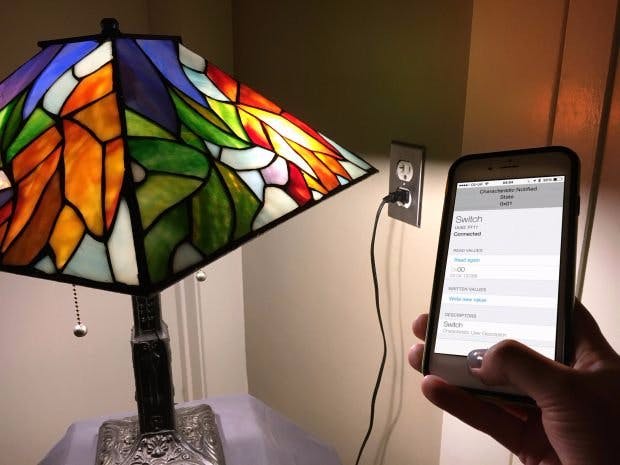
Now take a look at your Smart Light Switch in LightBlue (Figure C). Tapping through from the Smart Light Switch in the peripherals list, you can see the advertisement data for the service showing our two characteristics: Switch, which is Read/Write, and State, which is Notify. You can register the LightBlue app for notifications when the LED state changes by tapping on “Listen for notifications” in the State characteristic screen.
The Switch characteristic screen shows the current value of this characteristic, which should be 0x00, meaning the LED is off. Tap on “Write new value” to open the editor. Enter 01 and hit Done; the LED should turn on and the screen should show the new value as 0x01. If you registered for notifications, you should also see a drop-down to tell you the value has changed (Figure D).
If you have the Serial Console open you should also see the message Characteristic event: light on printed in the console. Finally, if you push the tactile button, you should see a further notification in LightBlue that the LED state has changed back to 0x00.
That’s it — you’ve created a working smart light switch!F
6. Connect a real light bulbNow connect your smart switch to an actual lamp. The PowerSwitch Tail (Figure E) simplifies our lives by hiding all that nasty AC electricity and letting us use a relay and our Arduino board to switch real mains-powered devices on and off. Nice.
Connect 3 wires to the PowerSwitch Tail’s screw terminals: the left terminal (labeled +in) is for +5V; the middle (labeled -in) is the signal wire; and the right is Ground. Then wire up the Arduino, switch, and PowerSwitch Tail as shown in Figure F.
Plug the PowerSwitch Tail into the wall, and then plug a mains-powered lamp or other electrical device (maximum draw 15A at 120V) into the PowerSwitch Tail socket.
The PowerSwitch Tail can be wired either as “normally open” or “normally closed.” From a safety perspective, it makes sense to use the normally open configuration here: Power will only flow while the signal wire from the Arduino is pulled LOW, otherwise the lamp remains “off.”
Since pulling the signal wire LOW rather than HIGH is what triggers the relay, we have to flip the logic for the LED_PIN. Go back into the code and you’ll see that everywhere there was a
digitalWrite(LED_PIN, HIGH);
we have changed it to
digitalWrite(LED_PIN, LOW);
and vice versa.
Now, instead of controlling an LED, you’re controlling a real lamp with your phone! Congrats!
This project is adapted from the book Make: Bluetooth by Alasdair Allan, Don Coleman, and Sandeep Mistry.
Alasdair Allan
 Sonia Wong


_3u05Tpwasz.png?auto=compress%2Cformat&w=40&h=40&fit=fillmax&bg=fff&dpr=2)
Comments