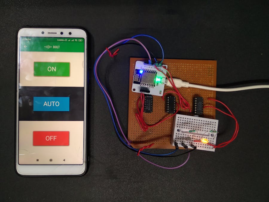
This project has primarily three functionalities i.e. to turn on the LED, to self-alter the intensity of the LED and to turn off the LED. These functions are controlled using three buttons designed in the Bolt Android app viz ON, AUTO and OFF respectively.When the AUTO button is clicked, the brightness of the LED is determined with respect to the light intensity of the surroundings using Light Detecting Resistor (LDR) or light sensor. The readings of the LDR are mapped to the range of the intensity of the LED and the variable output is generated using Pulse Width Modulation (PWM).If this system is used to monitor the light intensity of a photosensitive environment, such as a certain medicine storage, then a sudden change in light intensity can be harmful. This sudden change is detected using Z-score analysis and an alert system has been set up using Telegram Bot to notify the operator. The lights can then immediately be turned on or off using the app.
2. DEMONSTRATIONAlert Notification on Telegram
In this section we study the 'AUTO' functionality of the project i.e. automated change of the intensity of the LED based on the brightness of the surroundings. The brightness of the surroundings is measured using LDR.
3.1 Circuit Connections for LED and LDR
Given below are the circuit connections of LED and LDR with the bolt module for automated LED intensity based on the brightness of the surrounding s.
The input from the LDR is taken at analog pin A0 and the output to the LED is written at digital pin 0. LDR terminals don't have polarity. The power supply to the LDR is given using 3.3V pin of the bolt module. The resistance across LDR changes with change in light intensity falling on it. Since the Bolt Module cannot read resistance values, but it can read voltage values, hence a voltage divider circuit is made and the input to the Bolt module is the voltage across 10k resistance (since it is connected between an LDR terminal and ground) which depends on the resistance across LDR. The longer terminal of the LED is connected to the higher potential and the shorter terminal to the lower potential. Here the shorter terminal is connected to ground and the longer terminal is connected to the digital pin 0 through a series 330k resistor. The digital pin 0 output (dependent on LDR/A0 pin input) acts as the power supply for the LED and hence determines. its intensity
3.2 Configuration File
The python coding for this project has been done in Ubuntu (Linux). Before we start coding of the automating controlling of LED brightness in python, we need to make a configuration file which will have the specific keys for each user/device. We will import this file in our main code and use the various attributes. The advantage of this is that each user will only have to change the contents the configuration file to use the product.
The following is the configuration file (named as conf.py):
API_KEY = "XXXX"        //Bolt Cloud API Key
DEVICE_ID = "BOLTXXXX"    //Device ID of the Bolt Module
TELEGRAM_CHAT_ID = "-XXXX"    //Chat ID of the created Telegram Channel
TELEGRAM_BOT_ID = "botXXXX"    //Bot ID of the created Telegram Bot
FRAME_SIZE = 10        //Frame Size for Z score analysis
MUL_FACTOR = 1         //Multiplication factor for Z score analysis
The API key and Device ID of the Bolt module can be determined as follows:
- Connect your Bolt Device to the Bolt Cloud as per instructions given at https://cloud.boltiot.com/.
- The following screen will appear after that.The Bolt Device ID is highlighted in yellow.
- Go to the API section to know the API Key.
Section 2.5 explains how to obtain Telegram Chat ID and Telegram Bot ID and section and section 2.4 explains how to obtain Frame Size and Multiplication Factor
3.3 Mapping of LDR values to LED values
The range of values of the LDR are from 0 to 1024 and that of the LED is from 0 to 255. As evident, one to one mapping is not possible but an approximate 4:1 mapping can be done. It is done as follows:input_to_LED = 255 - (output_from_LDR / 4)The output from LDR is subtracted from 255 (maximum intensity of LED) because the mapping must be done inversely i.e. more brightness in the surroundings must correspond to less brightness of the LED.
3.4 Detection of Sudden Change in Light Intensity (Z-Score Analysis)
Z-score analysis is used for anomaly detection. Anomaly here means a variable's value (light intensity of the surroundings) going beyond a certain range of values. The range of values is called bounds (upper bound and lower bound). These bounds are calculated using the input values, frame size and multiplication factor. The frame size is the minimum number of input values needed for Z-score analysis and the multiplication factor determines the closeness of the bounds to the input values curve.
Given above is the formula to calculate the bounds. Here the input is represented as 'Vi', 'r' denotes the frame size and 'C' is the multiplication factor. Firstly we calculate the mean (Mn) of the input values (for every new input, the mean is calculated again). The variation of each input value (from the mean) is given as (Vi - Mn)^2. The Z-score (Zn) is calculated as shown above ( square root of the mean of the variation of each input value multiplied by the multiplication factor). The bounds are represented as 'Tn' and the upper bound is calculated as (Vi + Zn) and the lower bound is calculated as (Vi - Zn).
The frame size and multiplication factor are determined using trial-and-error method.
3.5 Creating Telegram Channel and Bot
Install the Telegram App and sign in using your mobile number. Then follow the following steps to create a telegram channel and bot.
In the configuration file, enter the Telegram Bot ID (or token) as shown in step 13.
To know the Telegram Chat ID, first send a message to the channel (the channel as shown in step 20). Then enter the following URL in your browser:
https://api.telegram.org/bot<token>/getUpdates
(omit '<' and '>' while entering the token)
A json array as shown below will appear having the Telegram Chat ID. The Telegram Chat ID is covered in red.
3.6 Complete Code for 'AUTO' functionality
;
import requests, json, time, math, statistics //import various python libraries
from boltiot import Bolt
//import the boltiot module from the Bolt python library
import conf                  //import the configuration file

//---------FUNCTION TO COMPUTE BOUNDS OR Z SCORE ANALYSIS------------//
def compute_bounds(history_data, frame_size, factor):
//Function to compute bounds
    if len(history_data) < frame_size:
        return none
    if len(history_data) > frame_size:
        del history_data[0:len(history_data) - frame_size]
    Mn = statistics.mean(history_data)
    Variance = 0
    for data in history_data:
        Variance += math.pow((data-Mn),2)
    Zn = factor * math.sqrt(Variance/frame_size)
    High_bound = history_data[frame_size -1] +Zn
    Low_bound = history_data[frame_size - 1] - Zn
    return [High_bound, Low_bound]    //Returns Low Bound and High Bound

//---------------FUNCTION FOR TELEGRAM ALERTS----------------------//
def send_telegram_message(message):
    url = "https://api.telegram.org/"+ conf.TELEGRAM_BOT_ID +"/sendMessage"
    data = {
            "chat_id": conf.TELEGRAM_CHAT_ID,
            "text": message
    }
    try:
        response = requests.request(
            "GET"
            url,
            params=data
        )
        print("Telegram response:")
        print(response.text)
        telegram_data = json.loads(response.text)
        return telegram_data["ok"]
    except Exception as e:
        print("An error occurred in sending the alert message via Telegram")
        print(e)
        return False
//-----------------------------------------------------------------//

mybolt = Bolt(conf.API_KEY, conf.DEVICE_ID)    //To identify your bolt device
history_data = []                //Array of input values from LDR

while True:

//---------------------READ INPUT FROM LDR--------------------------//
    response_ldr = mybolt.analogRead('A0')     //Read input from LDR at A0 pin
    ldr_data = json.loads(response_ldr)//Retrieve the input data in json format
    if ldr_data['success']!='1':
        print("There was an error while retrieving the data")
        print(ldr_data['value'])
        time.sleep(10)
        continue
    try:
        sensor_value = int(data_ldr['value'])
        //store current input value in variable
    except e:
        print("There was an error while parsing the response")
        print(e)
        continue
    print("LDR sensor value is: "+str(sensor_value)) //Print LDR input value
    print(response_ldr)

//----------------------MONITORING INTENSITY OF LED--------------------------//
    led_value_1 = int(sensor_value/4)
    if led_value-1 > 255:
        led_value_1 = 255
    led_value = 255 - led_value_1//Output value to LED based on LDR input value
    response_led = mybolt.analogWrite('0', led_value) //Write output at pin 0
    print("Automated LED value is: "+str(led_value)) //Print LED output value
    print(response_led)

//----------------PERFORMING Z SCORE ANALYSIS--------------------------//
    bound = compute_bounds(history_data, conf.FRAME_SIZE, conf.MUL_FACTOR)
    //Call compute_bounds function

//-------------COLLECTING SUFFICIENT DATA FOR Z SCORE ANALYSIS---------//
    if not bound:
    //If number of inputs are not sufficient to do Z score analysis
        required_data_count = conf.FRAME_SIZE - len(history_data) -1
        if (required_data_count != 0 and required_data_count != 1):
            print("Not enough data to compute Z score. Need",required_data_count,"more data points.")
        elif (required_data_count == 1):
            print("Not enough data to compute Z score. Need 1 more data point.")
        else:
            print("Enough data to compute Z score.")
        history_data.append(int(ldr_data['value']))
        //Append each new input to array history_data[]
        time.sleep(10)    //Wait for 10 seconds
        continue

//-----------DETECTING ANOMALY AND SENDING ALERTS--------------//
    try:
        if sensor_value > bound[0]: //If input crosses upper bound
            print("The light level has increased suddenly.")
            message = "The light intensity has increased suddenly. The current value is "+str(sensor_value)+". The automated LED intensity is "+str(led_value)+"."
            telegram_status = send_telegram_message(message)
            print("Telegram status:",telegram_status)
        elif sensor_value < bound[1]: //If input crosses lower bound
            print("The light level has decreased suddenly.")
            message = "The light intensity has decreased suddenly. The current value is "+str(sensor_value)+". The automated LED intensity is "+str(led_value)+"."
            telegram_status = send_telegram_message(message)
            print("Telegram status:",telegram_status)
        history_data.append(sensor_value)
        //Append each new input to array history_data[]
    except exception as e:
        print("Error")
        print(e)

    time.sleep(10)    //Wait for 10 seconds
2.7 Output Screenshots of Python Code (AUTO Functionality)
Using the digitalWrite() JavaScript function of the Bolt module, the output to LED can be given as 'HIGH' or 'LOW' to consequently turn on or off the LED. Only one input pin can be used for both the ON and OFF functionalities. Since digital pin 0 is used for the AUTO functionality, we use digital pin 1 for the ON/OFF functionality. But we cannot connect two different input pins to the LED at the same time. Hence to connect only one input to the LED at a time based on the choice of the user, we use a 2:1 multiplexer.
4.1 Concept of Multiplexer
The above diagram represents the functioning of a 2:1 multiplexer. From the truth table we see that, if the value of the select line is '0' or 'LOW' then the output is equal to Input 0 and if the value of the select line is '1' or 'HIGH' then the output is equal to Input 1. We give the select line input using the digital pin 2 of the Bolt module.We make the following conclusions:
- For ON/OFF functionality to work Select Line = '1' and so the the value of digital pin 2 must be written as 'HIGH' using digitalWrite() function.
- Furthermore, whether the LED will be ON or OFF will be decided by the value written to digital pin 1 i.e. 'HIGH' will indicate LED is ON and 'LOW' will indicate LED is OFF
- If Select Line = '0' then the system will function in the AUTO mode using the python program which will write values to digital pin 0 and automates the LED's intensity
4.2 Implementing 2:1 Multiplexer using Basic Gates
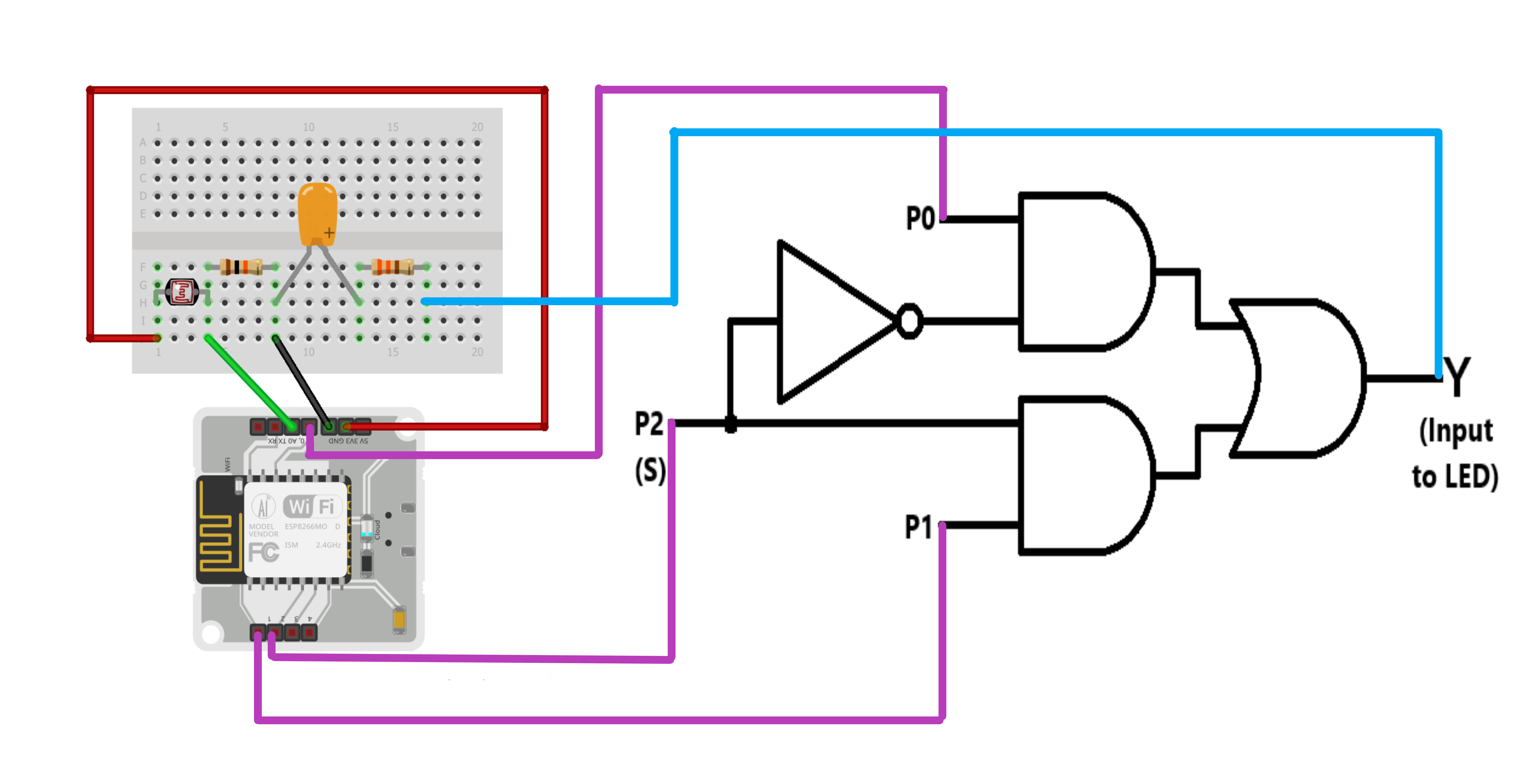
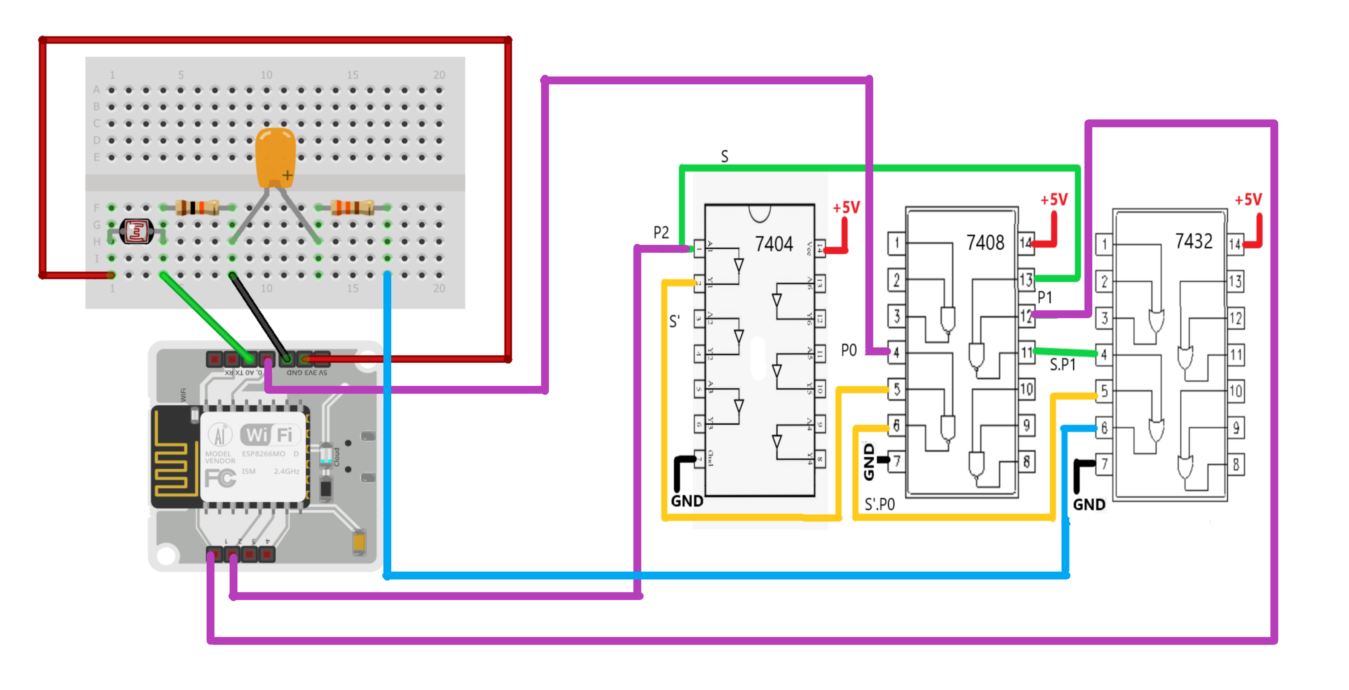
Let S represent the Select Line and S' its negation. Let P0, P1 and P2 represent the values of the digital pins 0, 1 and 2 respectively.The Boolean Function of 2:1 Multiplexer is as follows:Output = S'.P0 + S.P1 ; where S is the input from P2
As evident, to implement a multiplexer we need one NOT gate, two AND gates and one OR gate. The IC numbers of these gates are 7404, 7408 and 7432 respectively. The logic gate diagram and the implementation of a 2:1 multiplexer is as follows:
4.3 Setting up a Product on Bolt Cloud
Go to https://cloud.boltiot.com/ and then follow the steps below:
4.4 User Interface Design
The User Interface is designed using html and implemented using the Bolt Android app. The linking of the UI with the Bolt module is done using the JavaScript function digitalWrite().The html code is as follows:
<!DOCTYPE html>
<html>
   <head>
       <title>Automated Light Monitoring System</title>
       <script type="text/javascript" src="https://cloud.boltiot.com/static/js/boltCommands.js">
       </script>
       <script>
       setKey('{{ApiKey}}','{{Name}}');
       </script>
   </head>
   <body>
       <center>
       <div class="ON">
           <button class="button button1" onclick="digitalWrite(1, 'HIGH');digitalWrite(2, 'HIGH');">ON</button>
       </div>
       <div class="AUTO">
           <button class="button button2" onclick="digitalWrite(2, 'LOW');">AUTO</button>
       </div>
       <div class="OFF">
           <button class="button button3" onclick= "digitalWrite(1, 'LOW');digitalWrite(2, 'HIGH');">OFF</button>
       </div>
       </center>
       <style type="text/css">
           body {
               margin:0;
               padding:0;
           }
           div {
               height: 33.3vh;
               width: 60.9vh;
               align-content: center;
           }
           .ON{background-color: #FFFFFF;}
           .AUTO{background-color: #2f3640;}
           .OFF{background-color: #FFFFFF;}
           .button {
               border: none;
               color: white;
               padding: 15px 32px;
               text-align: center;
               width:200px;
               height:80px;
               text-decoration: none;
               display: block;
               font-size: 35px;
               font-family: Arial, Helvetica, sans-serif;
               box-shadow: 1px 1px 6px 0px black;
           }
           .button1 {background-color: #4CAF50;
               position: absolute;
               top: 10%;
               left:22%;
           }
           .button2 {background-color: #03A9F4;
               position: absolute;
               top: 43.5%;
               left:22%;
           }
           .button3 {background-color: #F44336;
               position: absolute;
               top: 76.5%;
               left:22%;
           }
       </style>
    </body>
</html>
The User Interface designed is as shown below:


Comments
Please log in or sign up to comment.