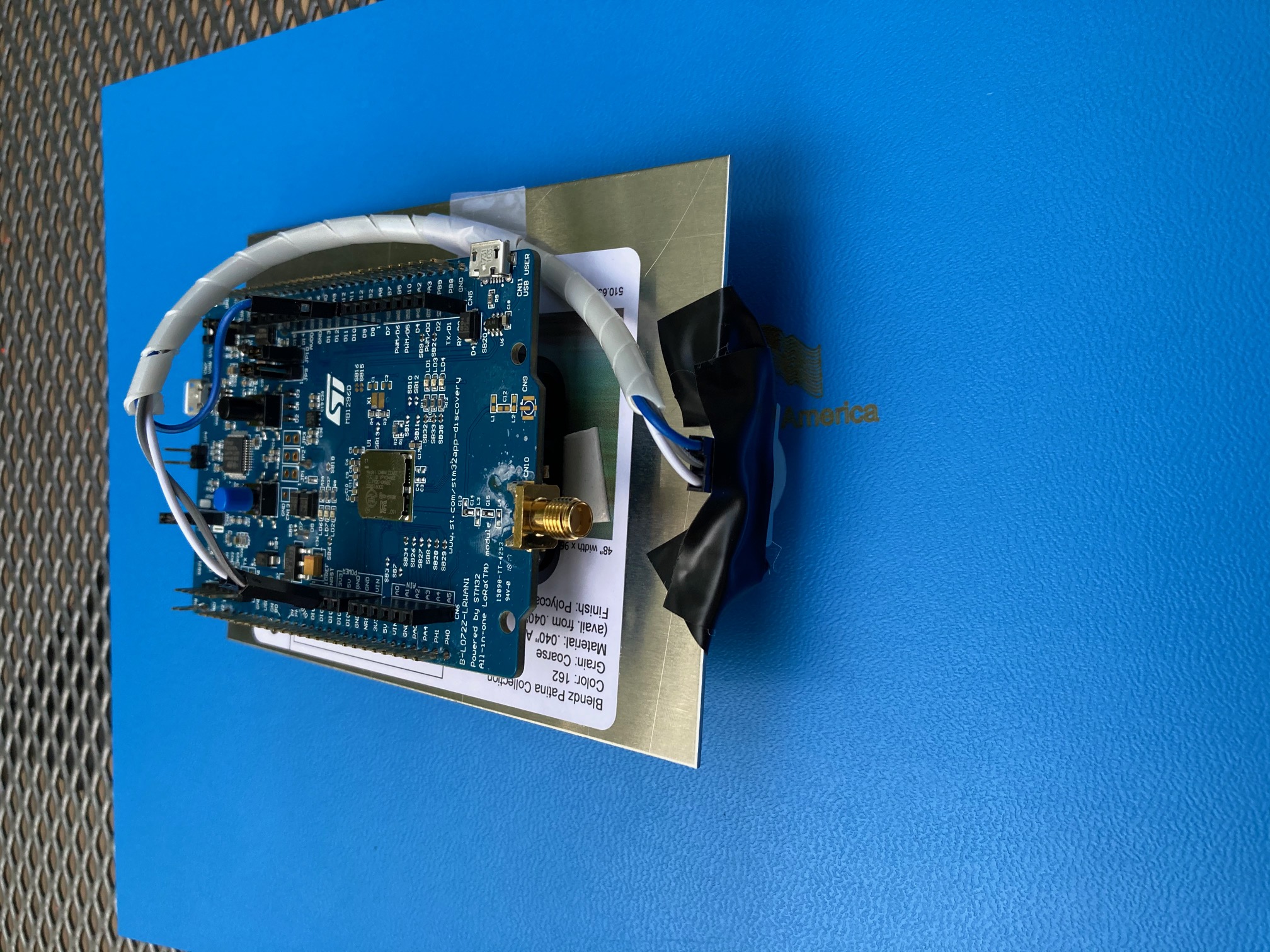
Modeling Covid19 spread is a challenging issue as it is difficult to accurately gauge human behavior. A key part of the models predicting the spread of Covid19 is footrafic and travel. However, there are not many on the ground sensors to aggregate data on travel metrics. Citizen science has long been a vehicle for collecting and parsing through data sets. I decided to make a LoRa enabled, affordable sensor to facilitate this citizen science in an easy way without a requirement of technical knowledge, or a large budget. The goal of this sensor is to be so inexpensive and simple, building one is easy. PeopleCount uses the STM32 LoRa Discovery board in conjunction with the Helium Network to create a simple sensor which works in any location with Helium Network coverage.
The goal of this project is to be easy to setup and to not require any technical knowledge
Setting up the Environment:Step 1: Download the file named "Programmer.zip" and double click to unzip it
Step 2: Go to https://www.st.com/en/development-tools/stsw-link009.html and follow the instructions to setup the proper software
Step 3: Reboot
Programming the Board:Step 1: Open the file arduino.exe in Programmer.zip
Step 2: Copy and paste the code index.ino into the editor
Step 3: Create a project on the Helium console and copy the pertinent information onto the top section where is says "FILLMEIN." (See https://developer.helium.com/devices/arduino-quickstart/st-discovery-lrwan1 for details)
Step 4: Go to Tools -> Boards and make sure B-L027-LRWAN1 is selected. Plug in your board using the provided cable and verify that it is selected under Tools -> Ports
Step 5: Click the arrow icon to program the board
Step 6: Enjoy a cup of coffee while the board is programmed
NOTE: If this method does not work, try the method explained at https://developer.helium.com/devices/arduino-quickstart/st-discovery-lrwan1
Step 1: Get your PIR sensor and check which pins are 5V, GND, and SIGNAL. This can vary from sensor to sensor. (Tip: The GND pin often will seem as if it isn't connected; The SIGNAL will often have a line (trace) which runs to a large IC; The 5V will often run to a part with 3 leads and a larger flat lead)
Step 2: Connect the sensor's 5V, GND and SIGNAL pins to 5V, GND and D8 respectively on the board.
Step 3: Wrap the wire from the sensor to the arduino in tape, mesh tubing or wire protectors to help prevent them from being cut. I used a wire protector in my build.
Step 4: Place a small piece of tape (ideally electrical tape) over the section of the board with the programming USB. Then place the PIR sensor there and tape it down. Make sure that no metal parts of the sensor are in contact with the board.
Step 5: Place the sensor in a plastic or wooden box (it must be weatherproofed) and cut a small hole for the PIR sensor to stick out of. Place the PIR sensor there and seal around with Hot Glue, Silicone Caulk, or any other weatherproofing material. Remember to make sure the container when shut is watertight.
Step 6: Decide whether you want to power the sensor via a USB power bank, solar panel, wall outlet or you want to power the sensor via 3 AA batteries. If you want to power it using batteries follow the instructions at https://developer.helium.com/devices/arduino-quickstart/st-discovery-lrwan1 under hardware setup.
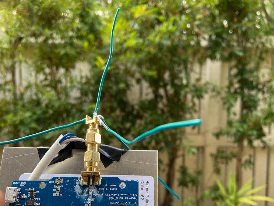
Technically after you finish those steps you are done, but for me that was not enough. I live in an area just far enough from Helium hotspots to not have coverage. The antenna provided in the development kit had limited reception and was better suited to being within 150 meters of a node for small IOT devices than for a truly off the grid sensor. The guide below details how to setup a simple antenna which should greatly increase the range of your sensor. This guide will be a little harder to follow and may require some specialized tools.
This antenna if built correctly has a VSWR of less than 1.2 and has more gain (because of the ground elements) than the stock "Rubber Duck" antenna.
Step 1: Take the SMA edge mount connector and break off all the legs except for the center pin.
Step 2: Cut 5 pieces of thick copper wire (if you hold it out it should stay straight) and cut it into 8.5 cm or 3.5 inch segments (NOTE: Cut the segments a little longer than needed as there will be a tuning step later).
Step 3: Solder 1 segment to each corner of the SMA connector and one straight up attached to the center pin.
Step 4: If you have a VNA now is the time to connect it to the antenna and begin trimming it to size. For those of us who do not have a VNA, just measure the height of the center element from the base of the connector and get it as close to but no shorter than 8.2 cm or 3.22 inches.
Step 5: If your SMA connector had a female end you are done. Otherwise add a female to female adapter to the end of the antenna.
Step 6: Enjoy your new 1/4 wave ground plane antenna and improved reception!
If you need even better reception, consider using a compact directional antenna (Yagi).
ConclusionThis sensor was meant to be a fun and easy weekend project that is incredibly exciting to build. Along the way I hope you learned about programming microcontrollers, enclosure construction techniques and the art of antenna design. If you enjoyed this project, I hope that you continue to build more and explore making more things with RF and electronics especially with Helium!
Next StepsThis sensor is wonderful on its own, but that is not what it is meant to do. Because it relies on the Helium network, it is easily scalable and can easily accommodate many sensors. My dream is that there will be at least one of these sensors on every street corner contributing to a vast dataset making Covid19 response more accurate and safer.
ThanksA vast majority of the setup code and instructions were derived from Helium's incredible developer resources. The console provided by Helium provided an invaluable tool in aggregating the data. Lastly, I wanted to thank Helium for providing the Helium Development Kit used in this project.


Comments
Please log in or sign up to comment.