This is a fairly simple IoT project with a lot of learning opportunities.
I'll begin with a detailed overview of the steps one should go through before directly diving into creating the final product. While there was already a lot of material on DIY robot cars available on the internet, a lot of painstaking days went by without any significant progress while working on this particular project, especially since I'm a fair beginner in the subject of IoT. So, I bring to you a step-by-step guide for how I successfully got through with this project and all the issues I ran into (and obviously how to overcome them).
First make sure to acquire all the hardware components listed above!
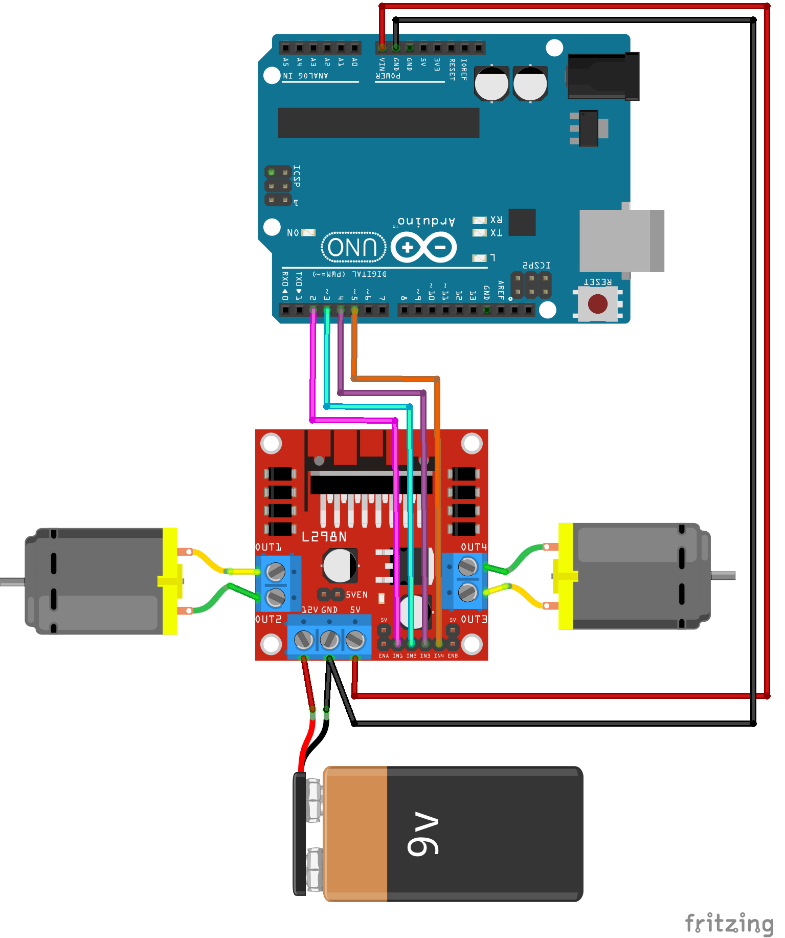
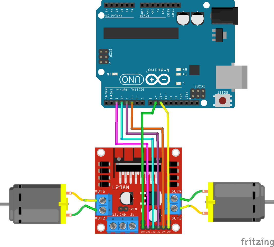
1. Arduino Uno and the motor drivers
I chose to work with L298N motor driver modules (because that is what the internet recommended). A detailed overview of how the motor drivers work and how to interface them with your Arduino board has been provided here. This webpage really helped me a lot in getting started with making my RC car.
I used 2 motor drivers to control my 4 motors. Due to a lack of GPIO pins on my Arduino board, I couldn't possibly write a program to control all 4 of the motors separately. Therefore, the only solution to my problem was to connect my two motor drivers in parallel. I appointed one motor driver for the rear and another for the front in my 4WD. So, my arrangement was such that when given a particular input, both the left motors (of both motor drivers) would undergo the same change (in speed and direction). As with the right motors in both front and rear.
Issues:
- Motors working with direct supply but not after connecting to motor driver. This could be because of low voltage supply or the motors are drawing more current than being supplied. First of all, make sure that your voltage supply is greater than 7V. Anything less than 6.5V may cause the motor driver to start fluctuating (flickering LED is a symptom of this) and the motors will not turn. Secondly, you need a battery which can supply current as required. Personally, I used 11.1V 3S 2200mAh 25/30C Li-Po Rechargeable Battery with XT60 connector. This was pretty expensive and I'd only recommend this to you if you plan on using the same for other projects (it is awesome for drone applications!) as I had to purchase more necessary accessories for it like the Male XT60 to Female JST adapter (to use the battery with jumper wires) and a Li-Po charger obviously. The main goal is to achieve a sufficiently large current supply, so you can look for a battery to satisfy your requirements.
- Both motors not rotating with the same speed. This again happens due to lack of required current supply. Your battery may be giving a voltage output of 12V, but one of the connected motors still might run at half the speed of the other, which will cause uneven movement after the final assembly is done. At least a 5A current supply would be enough for all 4 motors to run smoothly.
Here is a small code to test your motor driver and motors. Have fun with it by learning how to change the direction and speed of your motors! See what configuration makes the motors turn clockwise and anticlockwise and take a note of it - this will help later during the assembly so that you don't have to repeat this again at the end for determining which commands would make your RC car move forward and backward.
int motor1pin1 = 2;
int motor1pin2 = 3;
int motor2pin1 = 4;
int motor2pin2 = 5;
int speedx;
void setup() {
 pinMode(motor1pin1, OUTPUT);
 pinMode(motor1pin2, OUTPUT);
 pinMode(motor2pin1, OUTPUT);
 pinMode(motor2pin2, OUTPUT);
/*speed control pins*/
 pinMode(9, OUTPUT);
 pinMode(10, OUTPUT);
}
void loop() {
 //Controlling speed (0 = off and 255 = max speed):
 analogWrite(9, 50); //ENA pin
 analogWrite(10, 50); //ENB pin
 //Controlling spin direction of motors:
 digitalWrite(motor1pin1, LOW);
 digitalWrite(motor1pin2, HIGH);
 digitalWrite(motor2pin1, LOW);
 digitalWrite(motor2pin2, HIGH);
 delay(5000);
 analogWrite(9, 50);
 analogWrite(10, 50);
 delay(5000);
 /*digitalWrite(motor1pin1, LOW);
 digitalWrite(motor1pin2, HIGH);
 digitalWrite(motor2pin1, LOW);
 digitalWrite(motor2pin2, HIGH);
 delay(5000);*/
}
2. NodeMCU ESP8266 Generic Wi-Fi Module and MIT App Inventor: Turning an LED on and off
Before doing anything even remotely complicated using the NodeMCU and the App Inventor, it is best to test the waters by building a simple app to turn the built-in LED in the Wi-Fi module on and off!
I took help of this webpage which gives in-detail overview of what is MIT App Inventor, the code blocks, and the Arduino code. The only thing is that here the author shows how to control a relay. But the basic principle of the LED ON/OFF App is pretty much the same. For your NodeMCU, you can take reference from this code below:
#include <ESP8266WiFi.h>
#include <WiFiClient.h>
const char* ssid = "Wi-Fi ssid";
const char* password = "Wi-Fi password";
WiFiServer server(80);
void setup() {
 pinMode(LED_BUILTIN, OUTPUT);
 digitalWrite(LED_BUILTIN, 0);
 Serial.println();
 Serial.print("Connecting to ");
 Serial.print(ssid);
 WiFi.begin(ssid, password);
 while(WiFi.status() != WL_CONNECTED){
   delay(500);
   Serial.print(".");
 }
 Serial.println("");
 Serial.println("WiFi connected");
 server.begin();
 Serial.println("Server started");
 Serial.println(WiFi.localIP());
}
void loop() {
 WiFiClient client = server.available();
 if(!client){
   return;
 }
 Serial.println("New Client");
 while(!client.available()){
   delay(1);
 }
 String req = client.readStringUntil('\r');
 Serial.println(req);
 client.flush();
  int val;
 if (req.indexOf("/gpio/0") != -1){
   val = 0;
 }
 else if (req.indexOf("/gpio/1") != -1){
   val = 1;
 }
 else {
   Serial.println("invalid request");
   client.stop();
   return;
 }
 // Set GPIO2 according to the request
 digitalWrite(LED_BUILTIN, val);
 client.flush();
 String s = "HTTP/1.1 200 OK\r\nContent-Type: text/html\r\n\r\n<!DOCTYPE HTML>\r\n<html>\r\nGPIO is now ";
 s += (val)?"high":"low";
 s += "</html>";
Serial.println();
}
Issues:
- NodeMCU ESP8266 not working. If you are experiencing any particular error, then the best way to get rid of it is to just copy the error and look it up on the internet, because most of the time, hundreds of people have already experienced the exact same issue, and solutions are readily available. Otherwise, if you believe that your Wi-Fi module is faulty, follow through the instructions laid out on this webpage. If it doesn't work, then your module can very well be faulty or fake.
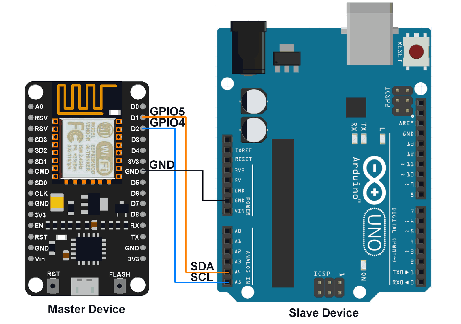
3. Arduino Uno and NodeMCU ESP8266 Interfacing: I2C Communication Protocol
This is an amazing source/guide to establish serial communication between the NodeMCU and Arduino. You can also see protocols other than I2C to interface the two boards, but I preferred I2C, simply because it seemed easier.
Now, after establishing a connection between them, we can finally use the same LED ON/OFF App we created in Step 2 to switch the built-in LED of Arduino on or off.
We only have to add a Wire library and a few commands to our previous NodeMCU code as follows:
#include <Wire.h>
#include <ESP8266WiFi.h>
#include <WiFiClient.h>
const char* ssid = "paya";
const char* password = "mishtynaina";
WiFiServer server(80);
void setup() {
 Serial.begin(115200);
 delay(10);
 Wire.begin(D1, D2);
 pinMode(LED_BUILTIN, OUTPUT);
 digitalWrite(LED_BUILTIN, 0);
 Serial.println();
 Serial.print("Connecting to ");
 Serial.print(ssid);
 WiFi.begin(ssid, password);
 while(WiFi.status() != WL_CONNECTED){
   delay(500);
   Serial.print(".");
 }
 Serial.println("");
 Serial.println("WiFi connected");
 server.begin(); //Capital S???
 Serial.println("Server started");
 Serial.println(WiFi.localIP());
}
void loop() {
 WiFiClient client = server.available();
 if(!client){
   return;
 }
 Serial.println("New Client");
 while(!client.available()){
   delay(1);
 }
 String req = client.readStringUntil('\r');
 Serial.println(req);
 client.flush();
  int val;
 if (req.indexOf("/gpio/0") != -1){
   val = 0;
   Wire.beginTransmission(8);
   Wire.write(val);
   Wire.endTransmission();
 }
 else if (req.indexOf("/gpio/1") != -1){
   val = 1;
   Wire.beginTransmission(8);
   Wire.write(val);
   Wire.endTransmission();
 }
 else {
   Serial.println("invalid request");
   client.stop();
   return;
 }
 // Set GPIO2 according to the request
 digitalWrite(LED_BUILTIN, val);
 client.flush();
 String s = "HTTP/1.1 200 OK\r\nContent-Type: text/html\r\n\r\n<!DOCTYPE HTML>\r\n<html>\r\nGPIO is now ";
 s += (val)?"high":"low";
 s += "</html>";
  Wire.requestFrom(8, 13); /* request & read data of size 13 from slave */
while(Wire.available()){
   char c = Wire.read();
 Serial.print(c);
}
Serial.println();
delay(1000);
}
And to receive the commands from NodeMCU, the Arduino code is as follows:
#include <Wire.h>
void setup() {
Wire.begin(8);                /* join i2c bus with address 8 */
Wire.onReceive(receiveEvent); /* register receive event */
Wire.onRequest(requestEvent); /* register request event */
Serial.begin(9600);           /* start serial for debug */
pinMode(13, OUTPUT);
}
void loop() {
delay(100);
}
// function that executes whenever data is received from master
void receiveEvent(int howMany) {
while (0 <Wire.available()) {
   int c = Wire.read();      /* receive byte as a character */
   if(c == 0){
     Serial.println(c);
     digitalWrite(13, c);
   }
   if(c ==1){
     Serial.println(c);
     digitalWrite(13, c);
   }
   //Serial.print(c);           /* print the character */
 }
Serial.println();             /* to newline */
}
// function that executes whenever data is requested from master
void requestEvent() {
Wire.write("Hello NodeMCU");  /*send string on request */
}
Issues:
- Working well while sending 0 and 1, but Arduino Serial Monitor printing a random value for numbers greater than 255. This is because only 8 bits can be sent or received at a time. For sending values greater than 255, we will have to use the Highbyte/Lowbyte method as follows:
Arduino code - Slave
if( Wire.available()>0){
byte low = Wire.read(); // read a byte of the buffer
byte high = Wire.read(); // read the next byte of the buffer.
int result = word (high, low); // melt them into an integer
}
NodeMCU code - Master
void requestEvent() {
int value = analogRead(_analogpinnumber); //reads analog analog pin
// create a buffer. This buffer can be used to send more than only 2 bytes.
byte buffer[10];
buffer[0] = lowByte (value);
buffer[1] = highByte ( value);
Wire.write( buffer, 2);
}
4. Making Joystick App and Receiving Values on NodeMCU
Here is a tutorial for making joysticks. I didn't follow it through word to word because the applications for the project in the tutorial and my own varied immensely. Besides that, a Bluetooth module was used in the given project as compared to my Wi-Fi module, which made the code blocks of my App Inventor very different from the blocks shown in this.
For reference, I have attached a .aia file for my joystick below.
5. Putting it all together
The final codes for the NodeMCU and Arduino Uno are also given below. You can find cheap 4WD car chassis online to assemble your final car. And voila! You made your own remote control car!
I had a lot of fun though all this time of building my RC car. At first I made it using an IR sensor so that I could simply control it with my TV remote, but the controls really didn't work as intuitively as I hopes they would. Hence the idea of making a Joystick app came into play. Now the car works very efficiently with really quick response time! I encountered a lot of hurdles, especially with the Wi-Fi module as it was my first time working with it (I even used ESP8266-01 at first, and struggled so much with it as I had ordered it without doing any significant research as to which Wi-Fi modules to use and which to not!)
All-in-all, this was a great learning experience (though frustrating at times) and I hope you have as much fun with it as I did!


_ztBMuBhMHo.jpg?auto=compress%2Cformat&w=48&h=48&fit=fill&bg=ffffff)


_3u05Tpwasz.png?auto=compress%2Cformat&w=40&h=40&fit=fillmax&bg=fff&dpr=2)
Comments
Please log in or sign up to comment.