


Hardware components | ||||||
 |
| × | 1 | |||
 |
| × | 1 | |||
 |
| × | 1 | |||
 |
| × | 5 | |||
 |
| × | 5 | |||
| × | 1 | ||||
 |
| × | 1 | |||
 |
| × | 1 | |||
Last summer, when I had to cook my own meals without living with the convenience of servery food, boiled eggs were my go-to breakfast. Soft boiled eggs with jammy yolks are the best, and achieving that perfection is all bout timing. It takes about 7-8 minutes once you put them in boiling water, but if you miss the mark, the yolk would get either overcooked or too runny. So I decided to build an eggtimer where you can set the timer based on your preferred level of cook. It also includes a temperature sensor that alerts you when the water starts boiling so that you can put your eggs in.
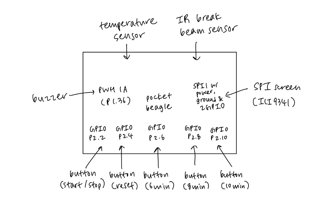
HardwarePocketBeagle was used as the microcontroller in this embedded system. Below is its pinout diagram for reference.
I first implemented five buttons on the breadboard. One side of the button should be grounded while the other side should be connected to 3.3V in the PocketBeagle, through a 1k resistor. The other end of the resistor connects to the GPIO pin in the PocketBeagle using a jumper wire. Since I set these buttons up in a separate breadboard, make sure to connect it to the main breadboard using additional jumper wires (+ to + and - to -).
Each button corresponds to each GPIO pin and function as below:
- yellow (P2_2) - resets timer
- red (P2_4) - stops timer
- blue (P2_6) - sets the timer to 6 minutes
- green (P2_8) - sets the timer to 8 minutes
- black (P2_10) - sets the timer to 10 minutes
Then I set up the buzzer. The buzzer generates a noise when the timer is over (when eggs are done cooking). The positive connection should be connected to the PWM pin (P2_1) of the PocketBeagle and negative connection to the ground.
Next is the SPI screen. It shows the timer counting down, display message when the time is up, and
Connect the pins of the screen as below:
- GND (black) to GND (P1_16)
- V_in (white) to 3.3V (P1_14)
- CLK (yellow) to CLK (P1_8)
- MISO (green) to MISO (P1_10)
- MOSI (blue) to MOSI (P1_12)
- CS (orange) to GPIO (P1_6)
- D/C (red) to GPIO (P1_4)
- RST (brown) to GPIO (P1_2)
The temperature sensor is the last component I implemented. The work is still in progress, but eventually it will be able to detect the temperature of the water and notifies the user when it starts boiling, which is 100 celsius degrees.
Wire the sensor as below:
- GND (black) to GND ( - rail of the breadboard)
- DAT (yellow) to PRU0 (P2_33)
- VCC (white) to power supply ( + rail of the breadboard)
All the instructions for the software are in the Github linked below.
Running the EggtimerThe video below shows the eggtimer running. (The device was set to 6 seconds instead of 6 minutes for the sake of testing.)
The next video shows the timer stopping when the red stop button is pressed, and resets when the yellow reset button is pressed.
Future DevelopmentThe software for the temperature sensor is currently set up in a way in which the buzzer beeps when the water reaches its boiling temperature (100 celsius), allowing the user to put their eggs. However, it is not functioning fully yet. Also, the IR break beam sensor can be implemented which can start the timer automatically after it detects the motion of the user putting eggs into the boiling pot.


_3u05Tpwasz.png?auto=compress%2Cformat&w=40&h=40&fit=fillmax&bg=fff&dpr=2)
Comments
Please log in or sign up to comment.