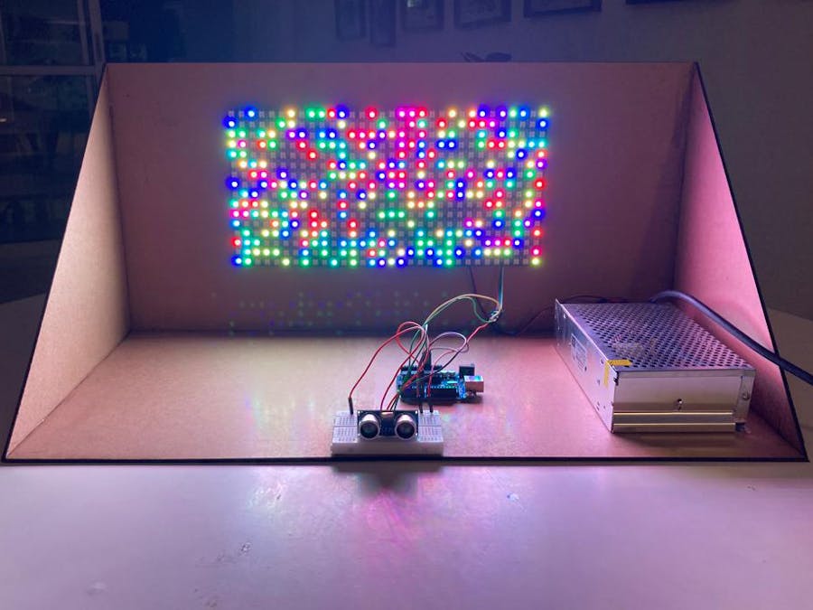
This is our first project with Arduino for the Digital Systems course in Computer Science graduation from Cesar School (Recife, Brazil).
Our final goal is to create a prototype of an Art Installation, a videowall made of a matrix of LED lights, creating an interactive panel of pixelated images that interacts with the public.
To achieve this goal, this is our first small step in the project: create a smaller version (32x16cm) led panel that randomly lights colorful pixels when the public walks in front of it, or interacts with the ultrasonic sensor.
1. Power SupplySetup
The 16x16 led matrix has 256 dots, since it is RGB, it has 768 leds with the typical 20mA each. So, all leds on max brightness will require 15.36A for just one matrix. Later, we concluded that we wouldn´t require even 50% of that power, and that it was easily manageable in code. Still, BE CAUTIOUS of the power supply that your project will require when dealing with led matrices and strips.
Leds usually works with 5V, same as the Arduino board.
First, the Arduino board won´t supply enough power for the leds, so you will need an external supply:
Then, connect the terminals:
Connect line, neutral and ground wires in the correct terminals:
(search about the wiring color codes, and double-check the indication signs)
Now, we need to power the LED matrix, as you can see on the photos below, we connected the 5V and a GND, in the middle, to the respective terminals of the power supply:
Connect:
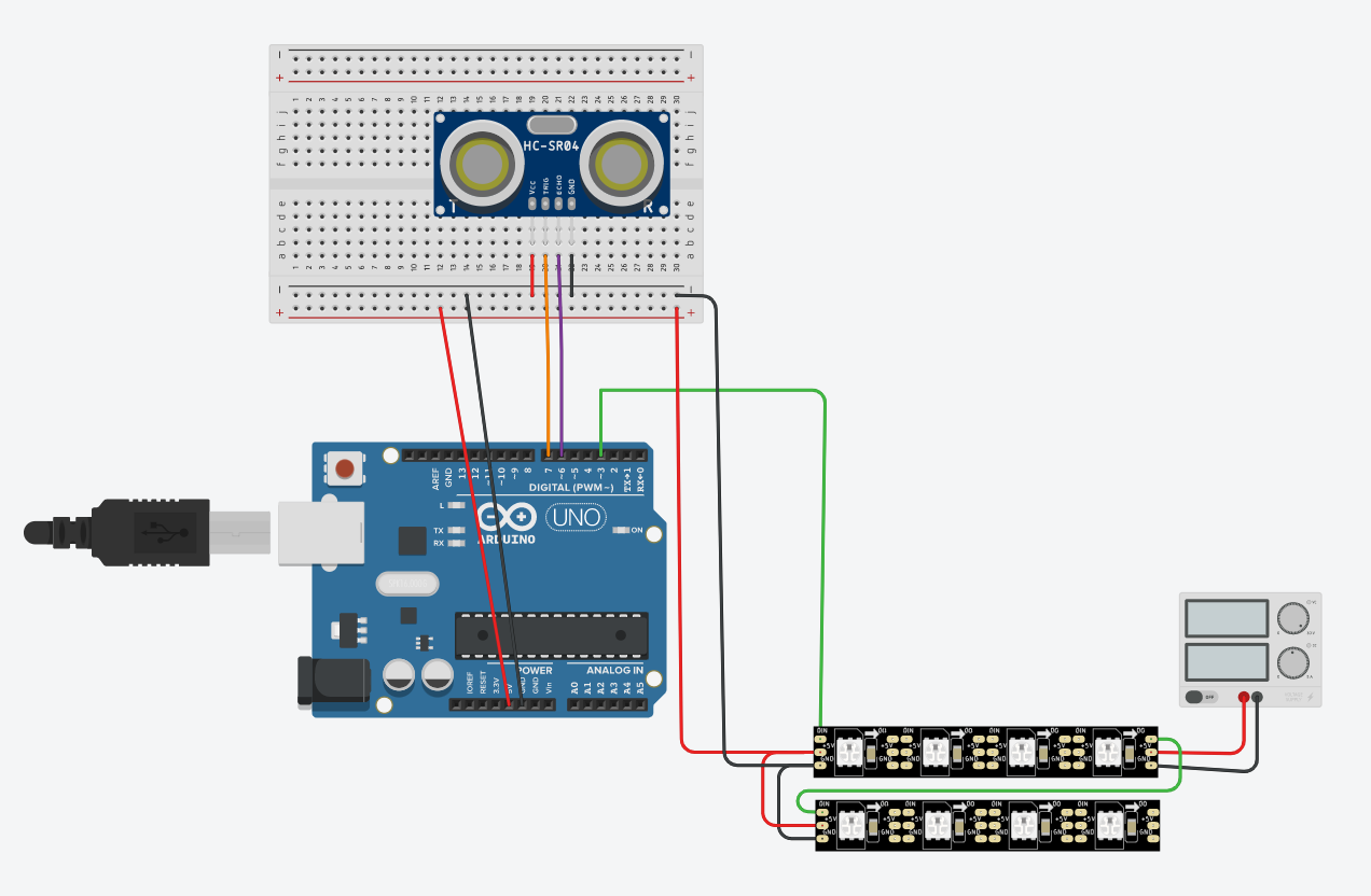
- The LED Panel's data in (DIN--to--3) Arduino´s.
- The LED Panel's ground (GND--to--GND) Arduino´s.
- The LED Panel's power line (5v--to--5v) Arduino´s.
*You can power the Arduino board and peripherals with thesame powersupply using the extra 5V terminals that the ledpanel provides, or just connect the GND and power the board through the USB or another power supply.
** Also you can use the breadboard to better organize the power as you´llsee later below.
From here, we could start testing our code to control the LED panel, but first we are going to add a second LED panel:
Just connect the output terminal from one panel to the input of the other:
3)UltrasonicSensorSetup
Connect:
Finally, put it all together:
4)Prototype Structure
We made a really simple structure just for better handling and showing.
We used three 60x30cm MDF boards, designed a box in MakerCase and adapted in Adobe Illustrator to laser cut it in LOUCo / Porto Digital.
.ai archive is available below.
5) CodeWe made use of Arduino IDE, FastLED library and Ultrasonic by Erick Simões library.
*We made a few tests with Adafruit´s NeoMatrix library, but wedidn´t use it in the code after all. We really recommend this library also, it works with FastLED and provides more features specificallyfor matrices. Since we are in a learning path, we decided to stick only to FastLED and keep it more simple and crude to better understandingthe principles.
We took some code samples and examples in fastLED´s github and Adafruit´s github, and with coberfranc´s instructables and HeathenHacks´ project.
More details in the code´s comments below.


Comments
Please log in or sign up to comment.