
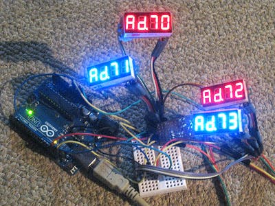
LED voltmeters are a cheap source of 7 segment displays and can easily be repurposed. Using the I2C protocol, a master microcontroller such as an Arduino Uno can govern multiple displays with just 2 I/O pins.
Now the Adafruit 4-digit 7-segment LED backpack is a handy little board, and Ladyada's tutorial and Arduino library make it a snap to use. It's as easy to connect 8 displays as a single one: just set them to have different slave addresses and hook them all up to your Arduino's I2C pins. The trouble is that 8 displays will set you back around $80 (or a little more if you like the colour blue). Looking around for an alternative, I discovered an internet retailer selling cheap LED voltmeters with slightly smaller displays. The listing titles mentioned "Stm8s003", the name of a series of small microcontrollers. For around $30 I bought myself 8 of the voltmeters and the STM8S discovery development board to reprogram them with. Similar voltmeters are available elsewhere, including eBay.
Then I had the most amazing stroke of luck. While I was waiting for the voltmeters to ship from the Far East, I came across an excellent blog post documenting a very similar project. The author had done an amazing job of writing firmware that would emulate the Adafruit board so that the hacked voltmeter would be compatible with the existing Arduino libraries. The hard work had all been done for me. All that remained to adapt the firmware to the slightly different voltmeter that I would be using.
HardwareThe voltmeters accepted between 3.5V to 30V on the red (V+) and black (V-) wires. On the reverse of I identified a voltage regulator that provided 3.3V to the STM8S003F3P6 MCU which drives the LEDs. One or two of the voltmeters looked slightly different with a trimmer resistor for R3 and and extra capacitor C1.
With soldering iron and tweezers in hand, I sacrificed one of the voltmeters to recreate the schematic as best I could. The hardware I2C pins on the MCU were both in use, but it was apparent that pins 19 and 20 on the MCU could be reassigned to bit bang the I2C protocol.
Next up, a step-by-step surgery guide to repurposing the voltmeters.
- Step 1. Orient the voltmeter face down with the chip on the left hand side. Desolder resistors R3 and RX. Solder a wire in hole 1 (marked with a square), trim and strip the loose end, and solder to the left hand pad under resistor RX. Solder two more wires into holes 4 and 5 of header HV. These connect to pins 4 (NRST) and 18 (SWIM) and are used in programming the STM8S chip.
- Step 2. Solder a wire to the pad marked "IN" next to the red wire that carries the positive voltage. The next part is slightly tricky. Apply flux to the very bottom pin on the left hand side the chip and very carefully solder to a length of solid core hookup wire. These two wires connect to pins 19 and 20 and carry the I2C SCL and SDA signals, respectively.
- Step 3. Add shrink wrap and hot glue for strain relief. Solder pin headers to the loose ends of the wires. Bada bing!
The firmware is archived in a github repository. As explained by the firmware's author, the majority of the source code is devoted to recreating the I2C slave protocol in software. The code is optimized to allow transfer speeds of up to 50kHz. An additional layer has been implemented to emulate the Adafruit Backpack. Because of the different pin assignments I made a few changes here and there.
The source code should be compiled using IAR Embedded Workbench for STMicroelectronics STM8. The “KickStarter” edition is usable free with registration. The STM8S/A Standard Peripherals Library (STM8S_StdPeriph_Driver V2.1.0) is required and can be downloaded as stsw-stm8069.zip from the http://www.st.com STM8 firmware page. . For one of the voltmeters, I had difficulty programming the MCU because it had Read-out Protection activated. I couldn't figure out how to disable this option using IAR Embedded Workbench, but it was straightforward to do from the "option bytes" menu in the STVD visual development IDE, which I also downloaded from http://www.st.com.
The STM8S discovery development board (see picture below) can be used to program the chip using the SWIM protocol. First remove the solder bridges connecting the emulator to the evaluation board, then connect the pins on the SWIM header to the correct terminals on the hacked voltmeter: VDD to V+, VSS to V-, NRST and SWIM to holes 4 and 5 of header HV, respectively.
Because the firmware emulates the Adafruit Backpack, the original Adafruit demo sketch can be used for testing. Just be aware that the Arduino I2C clock must first be reduced to 50 kHz by editing the TWI_FREQ variable in the Arduino /libraries/Wire/utility/twi.h file. To enable communication at the correct voltage the Arduino SCL and SDA pins, respectively, should be connected via a logic level converter to the wires joined to pins 19 and 20 on the display's MCU.
Photos- Github repository with details on the hardware, firmware, and documentation
- Detailed blog post for the original voltmeter hack
- Datasheet for the STM8S003F3P6 micro controller
- STM8S discovery development board
- STMicroelectronics homepage
- Turning Cheap Voltmeters into I2C Displays by Hack A Day on 2013-08-25
- I2C LED Display from Hacked Voltmeter by Dangerous Protypes on 2013-08-26


Comments