Each year, there are two to three million children who die of a vaccine-preventable disease and there are 19.4 million who are unable to receive basic immunization. One of the main reasons behind these figures is that the carrier boxes currently used to carry vaccines during the last miles of the delivery journey are incapable of sustaining the vaccines at the required temperature range for the entire duration of the journey. Vaccines should be stored under a specific temperature range which is 2˚ to 8˚ C; otherwise, the potency of the vaccine is lost. If the vaccine is kept at a temperature above or below the label, it could adversely affect the vaccine.
Whenever humans undergo a pandemic or any infectious disease vaccine plays a major economic cost. In 2020 world is undergoing the worst pandemic situation. Every researcher is trying to search vaccine against COVID-19. This is the primary challenge. The secondary challenge will be vaccination coverage. One of the reasons many countries lack enough vaccination coverage is insufficient cold storage in the vaccine supply chain. Despite the efficiency and benefits of the vaccines, factors such as lack of power supply, geographical ruggedness, and insufficient efficiency have prevented the spread of vaccine coverage in developing countries.
Vaccines are very crucial for treating preventable diseases, but they need a constant environment like maintenance of temperature. Currently, it is a barrier in the healthcare scenario. Vaccines should be stored under a specific temperature range which is 2˚ to 8˚ C; otherwise, the potency of the vaccine is lost. If the vaccine is kept at a temperature above or below the label, it could adversely affect the vaccine.
This project mainly deals with the upgradation of a thermally insulated cold box that can store 12-15 vials and can be tracked using sensors and can provide sensor’s information to a cloud server. Data can be visualized from a web dashboard. The user also gets an instant notification in case of any abnormality such as a temperature increase.
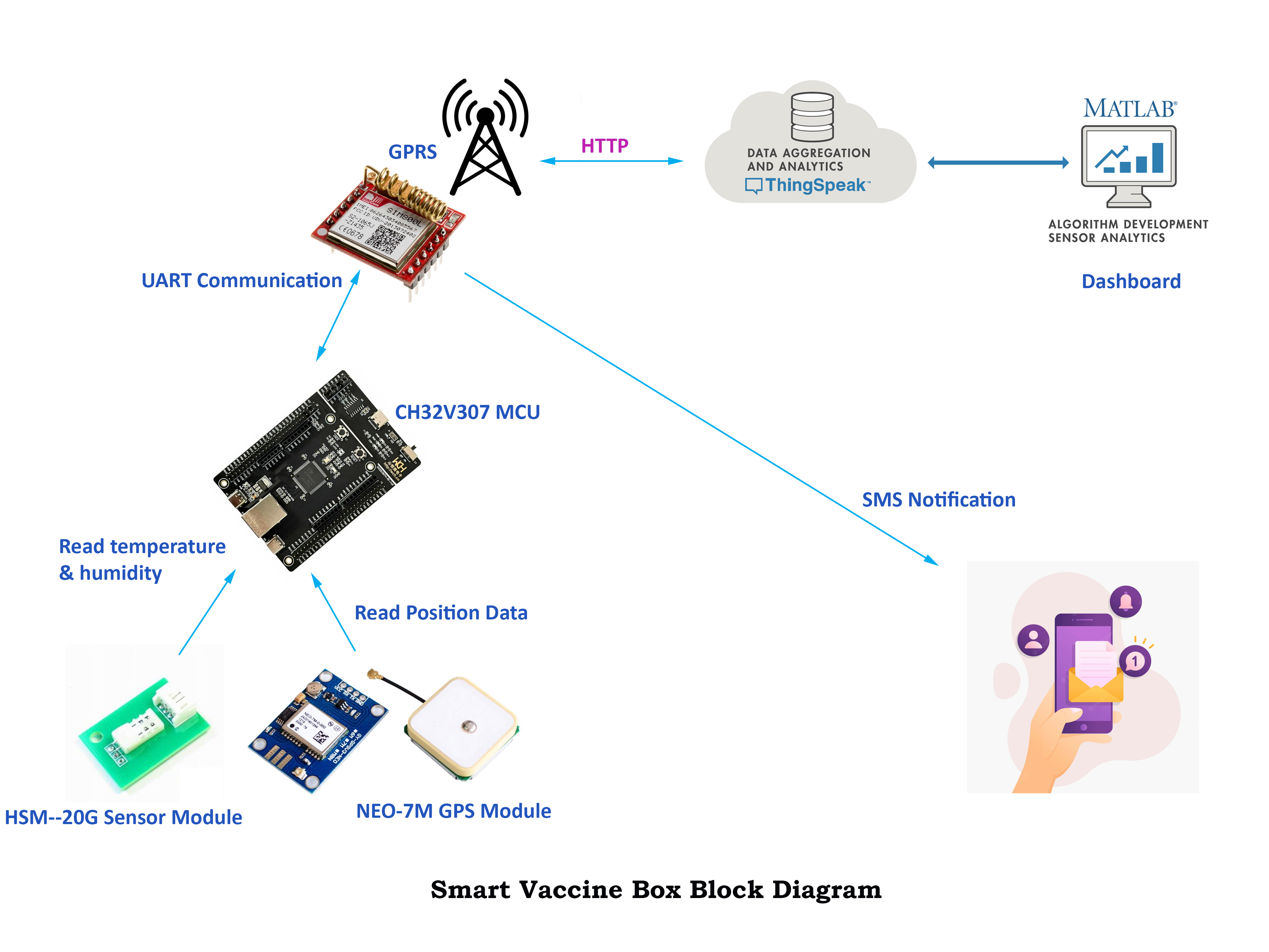
How the System WorksThe following block diagram shows a complete picture of my project. The main unit or brain of the system is the WCH CH32V307 RISC-V microcontroller development board.
The board collects the temperature and humidity data from an analog temperature and humidity sensor. The sensor is placed inside the vaccine box. A GPS module provides the location of the vaccine box to the microcontroller. The GPS module is connected to the microcontroller using a UART port. A SIM800 GPRS/GSM module is connected to the microcontroller using another UART port. After collecting the temperature, humidity, and position data the microcontroller sends those data to the ThingSpeak cloud using GPRS data for further analysis, visualization, and storage. Data can be remotely visualized from a web dashboard. The SIM800 module is also used to send emergency SMS notifications for any abnormal change in temperature and humidity data. There is also an LCD display in the system that helps to see the information from the device.
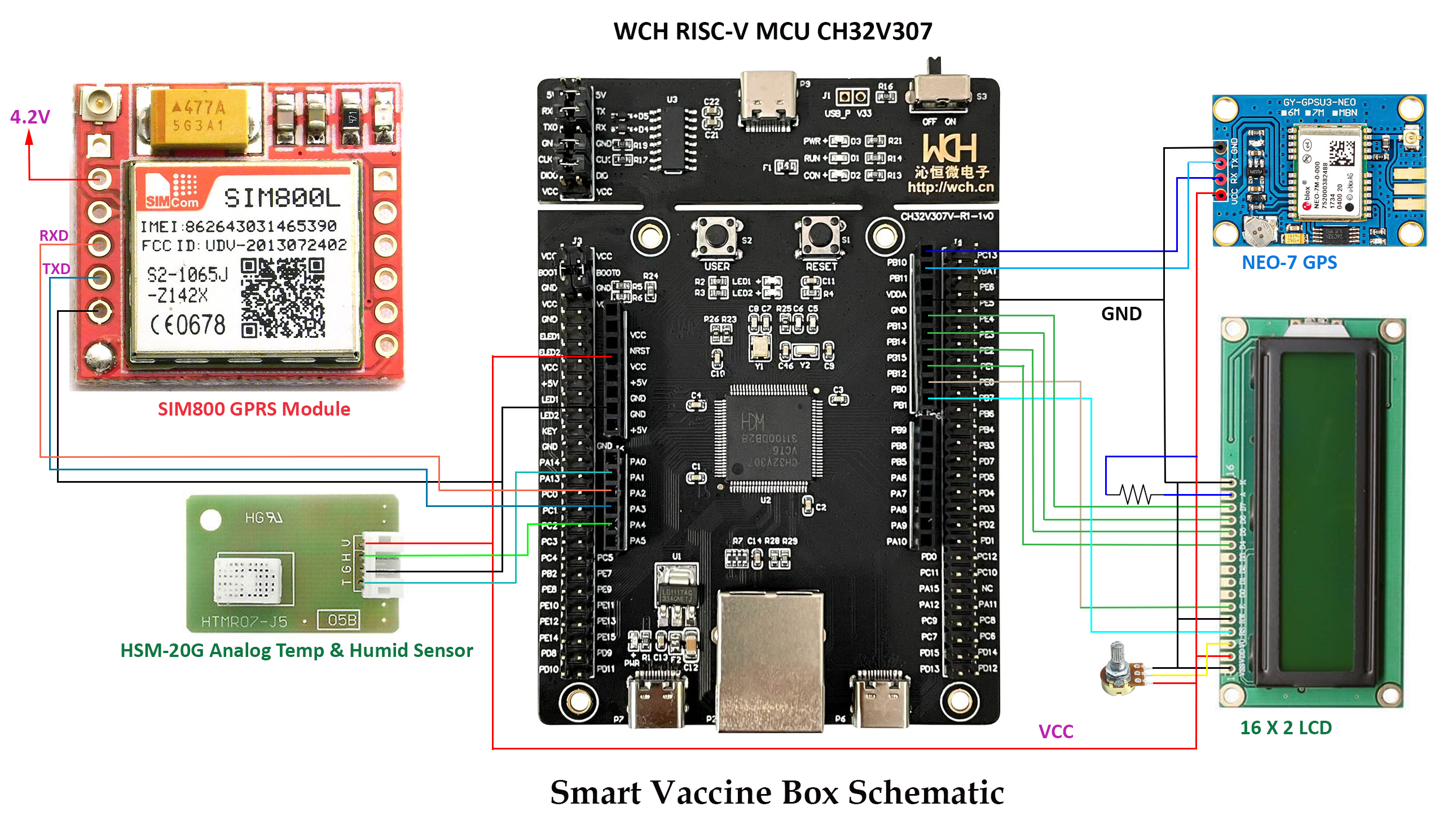
The ConnectionsThe following image shows the connections between the microcontroller and other sensors and modules.
The temperature and humidity sensor is connected to two analog channels of the microcontroller. SIM800 module is connected through UART port 2 and the GPS module is connected to UART port 3 of the microcontroller board. The LCD display is connected through 6 pins of port B of the microcontroller. The following picture shows the breadboard prototype of the system.
The following picture was taken while developing the code for the project. The code was developed based on RT-Thread OS using MounRiver studio.
In the photo above, LCD is showing the temperature, humidity, and the location that was taken from the sensor and the GPS module. For perfectly working the SIM800 module should be powered from a separate 4.2V supply that is capable of at least 1A for a short period of time.
Writing the CodeThe code for the project is developed based on the RT-Thread OS. RT-Thread is mainly written in C language, easy to understand, and easy to port(can be quickly port to a wide range of mainstream MCUs and module chips). It applies object-oriented programming methods to real-time system design, making the code elegant, structured, modular, and very tailorable.
I developed the code in MounRiver Studio. I first tried to develop the code using RT-Thread Studio but failed to successfully run the hex/elf file to the CH32V307 Development Kit. Then I migrated to MounRiver Studio.
Code for LCD
After successfully running the GPIO_Toggle example in both RT-Thread and Non RT-Thread version I started developing a library for Hitachi HD44780 LCD display as I did not find any existing working library for the CH32V307 microcontroller. The following code snippet is for LCD display initialization in 4-bit mode based on RT-Thread.
void rt_lcd_init(void)
{
    rt_pin_mode(RS, PIN_MODE_OUTPUT);
    rt_pin_mode(EN, PIN_MODE_OUTPUT);
    rt_pin_mode(D4, PIN_MODE_OUTPUT);
    rt_pin_mode(D5, PIN_MODE_OUTPUT);
    rt_pin_mode(D6, PIN_MODE_OUTPUT);
    rt_pin_mode(D7, PIN_MODE_OUTPUT);

    //Now we pull both RS and R/W low to begin commands
    rt_pin_write(RS, PIN_LOW);
    rt_pin_write(EN, PIN_LOW);
    rt_thread_mdelay(15);

    rt_lcd_command(0x03); //4 bit mode
    rt_thread_mdelay(5);

    rt_lcd_command(0x03); //4 bit mode
    rt_thread_mdelay(5);

    rt_lcd_command(0x03); //4 bit mode
    rt_thread_mdelay(5);

    rt_lcd_command(0x02); //4 bit mode
    rt_thread_mdelay(1);

    rt_lcd_command(LCD_FUNCTIONSET | 0x08); //first try
    rt_thread_mdelay(5);

    rt_lcd_command(LCD_FUNCTIONSET | 0x08); //second try
    rt_thread_mdelay(1);

    rt_lcd_command(LCD_FUNCTIONSET | 0x08); //final go
    rt_lcd_command(LCD_FUNCTIONSET | 0x08); //final go

    rt_lcd_command(LCD_DISPLAYON | LCD_CURSOROFF | LCD_BLINKOFF | LCD_DISPLAYCONTROL);

    rt_lcd_command(LCD_CLEARDISPLAY);
    rt_thread_mdelay(2);

    rt_lcd_command(LCD_ENTRYLEFT | LCD_ENTRYSHIFTDECREMENT | LCD_ENTRYMODESET);

    rt_lcd_setRowOffsets(0x00, 0x40, 0x00 + 16, 0x40 + 16);
    //rt_hw_us_delay(100);
}
The following code snippet shows two functions for writing data and command in the LCD display.
void rt_lcd_command(uint8_t data){

    rt_pin_write(RS, PIN_LOW);
    rt_pin_write(EN, PIN_HIGH);
    rt_uint8_t data_first = data>>4;
    rt_uint8_t data_last = data;
    rt_uint8_t i;
    for (i = 0; i < 4; ++i) {
       rt_pin_write(data_pins[i], (data_first >> i) & 0x01);
    }
    rt_pin_write(EN, PIN_LOW);
    rt_thread_mdelay(1);
    rt_pin_write(EN, PIN_HIGH);
    for (i = 0; i < 4; ++i) {
       rt_pin_write(data_pins[i], (data_last >> i) & 0x01);
    }
    rt_pin_write(EN, PIN_LOW);
    rt_thread_mdelay(1);
}


void rt_lcd_data(uint8_t data){

    rt_pin_write(RS, PIN_HIGH);
    rt_pin_write(EN, PIN_HIGH);
    rt_uint8_t data_first = data>>4;
    rt_uint8_t data_last = data;
    rt_uint8_t i;
    for (i = 0; i < 4; ++i) {
       rt_pin_write(data_pins[i], (data_first >> i) & 0x01);
    }
    rt_pin_write(EN, PIN_LOW);
    rt_thread_mdelay(1);
    rt_pin_write(EN, PIN_HIGH);
    for (i = 0; i < 4; ++i) {
       rt_pin_write(data_pins[i], (data_last >> i) & 0x01);
    }
    rt_pin_write(EN, PIN_LOW);
    rt_thread_mdelay(1);
}
Code for Temperature & Humidity Sensor
I used the HSM-20G sensor for reading temperature and humidity. This is an analog sensor that provides temperature and humidity data in two separate analog pins. So, I used two analog channels of the microcontroller for reading temperature and humidity. The following code shows the analog channel configuration in MounRiver studio.
void  ADC_Function_Init(void)
{
    ADC_InitTypeDef ADC_InitStructure={0};
    GPIO_InitTypeDef GPIO_InitStructure={0};

    RCC_APB2PeriphClockCmd(RCC_APB2Periph_GPIOA , ENABLE );
    RCC_APB2PeriphClockCmd(RCC_APB2Periph_ADC1  , ENABLE );
    RCC_APB2PeriphClockCmd(RCC_APB2Periph_ADC2  , ENABLE );
    RCC_ADCCLKConfig(RCC_PCLK2_Div4);

    GPIO_InitStructure.GPIO_Pin = GPIO_Pin_1 |GPIO_Pin_4;
    GPIO_InitStructure.GPIO_Mode = GPIO_Mode_AIN;
    GPIO_Init(GPIOA, &GPIO_InitStructure);

    ADC_DeInit(ADC1);
    ADC_DeInit(ADC2);

    ADC_InitStructure.ADC_Mode = ADC_Mode_InjecSimult;
    ADC_InitStructure.ADC_ScanConvMode = DISABLE;
    ADC_InitStructure.ADC_ContinuousConvMode = DISABLE;
    ADC_InitStructure.ADC_ExternalTrigConv = ADC_ExternalTrigInjecConv_None;
    ADC_InitStructure.ADC_DataAlign = ADC_DataAlign_Right;
    ADC_InitStructure.ADC_NbrOfChannel = 1;
    ADC_InitStructure.ADC_OutputBuffer = ADC_OutputBuffer_Disable;
    ADC_InitStructure.ADC_Pga = ADC_Pga_1;

    ADC_Init(ADC1, &ADC_InitStructure);
    ADC_InjectedSequencerLengthConfig(ADC1, 1);
    ADC_InjectedChannelConfig(ADC1, ADC_Channel_1, 1, ADC_SampleTime_239Cycles5 );

    ADC_Cmd(ADC1, ENABLE);

    ADC_BufferCmd(ADC1, DISABLE);   //disable buffer
    ADC_ResetCalibration(ADC1);
    while(ADC_GetResetCalibrationStatus(ADC1));
    ADC_StartCalibration(ADC1);
    while(ADC_GetCalibrationStatus(ADC1));
    Calibrattion_Val1 = Get_CalibrationValue(ADC1);

    ADC_BufferCmd(ADC1, ENABLE);   //enable buffer

    ADC_Init(ADC2, &ADC_InitStructure);
    ADC_InjectedSequencerLengthConfig(ADC2, 1);
    ADC_InjectedChannelConfig(ADC2, ADC_Channel_4, 1, ADC_SampleTime_239Cycles5 );

    ADC_SoftwareStartInjectedConvCmd(ADC2, ENABLE);
    ADC_Cmd(ADC2, ENABLE);

    ADC_BufferCmd(ADC2, DISABLE);   //disable buffer
    ADC_ResetCalibration(ADC2);
    while(ADC_GetResetCalibrationStatus(ADC2));
    ADC_StartCalibration(ADC2);
    while(ADC_GetCalibrationStatus(ADC2));
    Calibrattion_Val2 = Get_CalibrationValue(ADC2);

    ADC_BufferCmd(ADC2, ENABLE);   //enable buffer
}
The following function reads the analog data from the temperature sensor and converts the analog value first in milli-volts and then in temperature.
s32 get_temp_value(void)
{
    ADC_SoftwareStartInjectedConvCmd(ADC1, ENABLE);
    rt_thread_mdelay(100);
    ADC_SoftwareStartInjectedConvCmd(ADC1, DISABLE);
    rt_thread_mdelay(100);

    while(!ADC_GetFlagStatus(ADC1, ADC_FLAG_JEOC ));
        u16 adc_value = ADC_GetInjectedConversionValue(ADC1, ADC_InjectedChannel_1);

    int i = 0;
    s32 converted_value = 0;
    s32 value_mv = 0;
    //averaging 15 readings for better accuracy
    for(i=0; i<15; i++)
    {
        converted_value = Get_TEMP_ConversionVal(adc_value);
        value_mv += (converted_value * 3300 / 4096);
    }
    value_mv = value_mv/15;
    s32 temperature = ((-0.00015 * value_mv * value_mv) + (value_mv * 0.2268) - 11.4945);

    rt_kprintf( "Temp  =%d\r\n", temperature);

    return temperature;
}
Code for SIM800 GSM/GPRS Module
The SIM800 module is used to send the sensor and position data to the cloud for storing, visualization and analysis. The microcontroller sends data to the SIM800 module using the UART2 port. So, the usart2 port is configured using the following lines to enable it.
void usart2_configuration(void)
{
    GPIO_InitTypeDef  GPIO_InitStructure = {0};
    USART_InitTypeDef USART_InitStructure = {0};
    NVIC_InitTypeDef  NVIC_InitStructure = {0};

    RCC_APB1PeriphClockCmd(RCC_APB1Periph_USART2, ENABLE);
    RCC_APB2PeriphClockCmd(RCC_APB2Periph_GPIOA, ENABLE);

    /* USART2 TX-->PA2  RX-->PA3 */
    GPIO_InitStructure.GPIO_Pin = GPIO_Pin_2;
    GPIO_InitStructure.GPIO_Speed = GPIO_Speed_50MHz;
    GPIO_InitStructure.GPIO_Mode = GPIO_Mode_AF_PP;
    GPIO_Init(GPIOA, &GPIO_InitStructure);
    GPIO_InitStructure.GPIO_Pin = GPIO_Pin_3;
    GPIO_InitStructure.GPIO_Mode = GPIO_Mode_IN_FLOATING;
    GPIO_Init(GPIOA, &GPIO_InitStructure);

    USART_InitStructure.USART_BaudRate = 9600;
    USART_InitStructure.USART_WordLength = USART_WordLength_8b;
    USART_InitStructure.USART_StopBits = USART_StopBits_1;
    USART_InitStructure.USART_Parity = USART_Parity_No;
    USART_InitStructure.USART_HardwareFlowControl = USART_HardwareFlowControl_None;
    USART_InitStructure.USART_Mode = USART_Mode_Tx | USART_Mode_Rx;

    USART_Init(USART2, &USART_InitStructure);
    USART_ITConfig(USART2, USART_IT_RXNE, ENABLE); //USART_IT_RXNE - Receive Data register not empty interrupt.

    NVIC_PriorityGroupConfig(NVIC_PriorityGroup_2);
    NVIC_InitStructure.NVIC_IRQChannel = USART2_IRQn;
    NVIC_InitStructure.NVIC_IRQChannelPreemptionPriority = 2;
    NVIC_InitStructure.NVIC_IRQChannelSubPriority = 2;
    NVIC_InitStructure.NVIC_IRQChannelCmd = ENABLE;
    NVIC_Init(&NVIC_InitStructure);

    USART_Cmd(USART2, ENABLE);
}

void USART2_IRQHandler(void)
{
    if(USART_GetITStatus(USART2, USART_IT_RXNE) != RESET)
    {
        rt_kprintf("%c", USART_ReceiveData(USART2));

    }
}
The following function sends the data to the ThingSpeak IoT cloud using the HTTP protocol.
void send_data(char *msg, int first_val, int second_val){
    rt_thread_mdelay(1000);
    send_command("AT\r\n");       // Check Communication
    rt_thread_mdelay(500);
    send_command("AT+SAPBR=3,1,\"CONTYPE\",\"GPRS\"\r\n");  // Connection type GPRS
    rt_thread_mdelay(500);
    send_command("AT+SAPBR=3,1,\"APN\",\"gpinternet\"\r\n"); // APN of the provider
    rt_thread_mdelay(500);
    send_command("AT+SAPBR=1,1\r\n");  // Open GPRS context
    rt_thread_mdelay(4000);
    send_command("AT+SAPBR=2,1\r\n");    // Query the GPRS context
    rt_thread_mdelay(3000);
    send_command("AT+HTTPINIT\r\n"); // Initialize HTTP service
    rt_thread_mdelay(3000);
    send_command("AT+HTTPPARA=\"CID\",1\r\n");   // Set parameters for HTTP session
    rt_thread_mdelay(3000);
    send_command("AT+HTTPPARA=\"URL\",\"api.thingspeak.com/update\"\r\n"); // Set parameters for HTTP session
    rt_thread_mdelay(5000);
    send_command("AT+HTTPDATA=33,10000\r\n");  // POST data of size 33 Bytes with maximum latency time of 10seconds for inputting the data
    rt_thread_mdelay(2000);

    send_apikey(msg, first_val, second_val);
    rt_thread_mdelay(5000);

    send_command("AT+HTTPACTION=1\r\n");      // Start POST session
    rt_thread_mdelay(3000);
    send_command("AT+HTTPTERM\r\n");       // Terminate HTTP service
    rt_thread_mdelay(3000);
    send_command("AT+SAPBR=0,1\r\n");   // Close GPRS context
    rt_thread_mdelay(2000);
}

void send_command(u8 *buf){
    u8 *command, count = 0;
    command = buf;
    while(count < strlen(command))
        {
            USART_SendData(USART2, command[count++]);
            while(USART_GetFlagStatus(USART2, USART_FLAG_TXE) == RESET) /* waiting for sending finish */
            {
            }
        }
}
The Main Code
Four separate thread was created in the main code for reading the sensor, reading the position, displaying data to LCD, and sending the data to the cloud.
void Run(void)
{

    /**********Creating the threads************/
    read_sensor_thread =                            //thread control block pointer
        rt_thread_create( "ReadSensor",             //thread name
                          read_sensor,              //thread entry function
                          RT_NULL,                  //thread entry function parameters
                          512,                      //thread stack size
                          1,                        //thread priority
                          20);                      //thread time slice
        if (read_sensor_thread != RT_NULL)
            rt_thread_startup(read_sensor_thread);  //make the thread enter the ready state

    display_thread = rt_thread_create("Display", display, RT_NULL, 512, 2, 20);
    if (display_thread != RT_NULL)
        rt_thread_startup(display_thread);

    read_location_thread = rt_thread_create("Location", read_location, RT_NULL, 512, 2, 20);
    if (read_location_thread != RT_NULL)
         rt_thread_startup(read_location_thread);

    data_to_cloud_thread = rt_thread_create( "DataToCloud", data_to_cloud, RT_NULL, 512, 2, 20);
    if (data_to_cloud_thread != RT_NULL)
        rt_thread_startup(data_to_cloud_thread);

    notification_thread = rt_thread_create( "SendNotification", send_notification, RT_NULL, 512, 2, 20);
    if (notification_thread != RT_NULL)
        rt_thread_startup(notification_thread);

}
The following screenshot shows the organization of the libraries and the main program.
The GitHub repository link of the complete project is attached in the code section. You can download the repo on your PC and directly compile and run the project. You need to install the MounRiver studio for opening the project.
If you face any issues with Debug & Peripheral folder after opening the project with MounRiver studio, manually copy the contents of the folders from the downloaded files and paste those files into the corresponding folder of the MounRiver Studio Project.
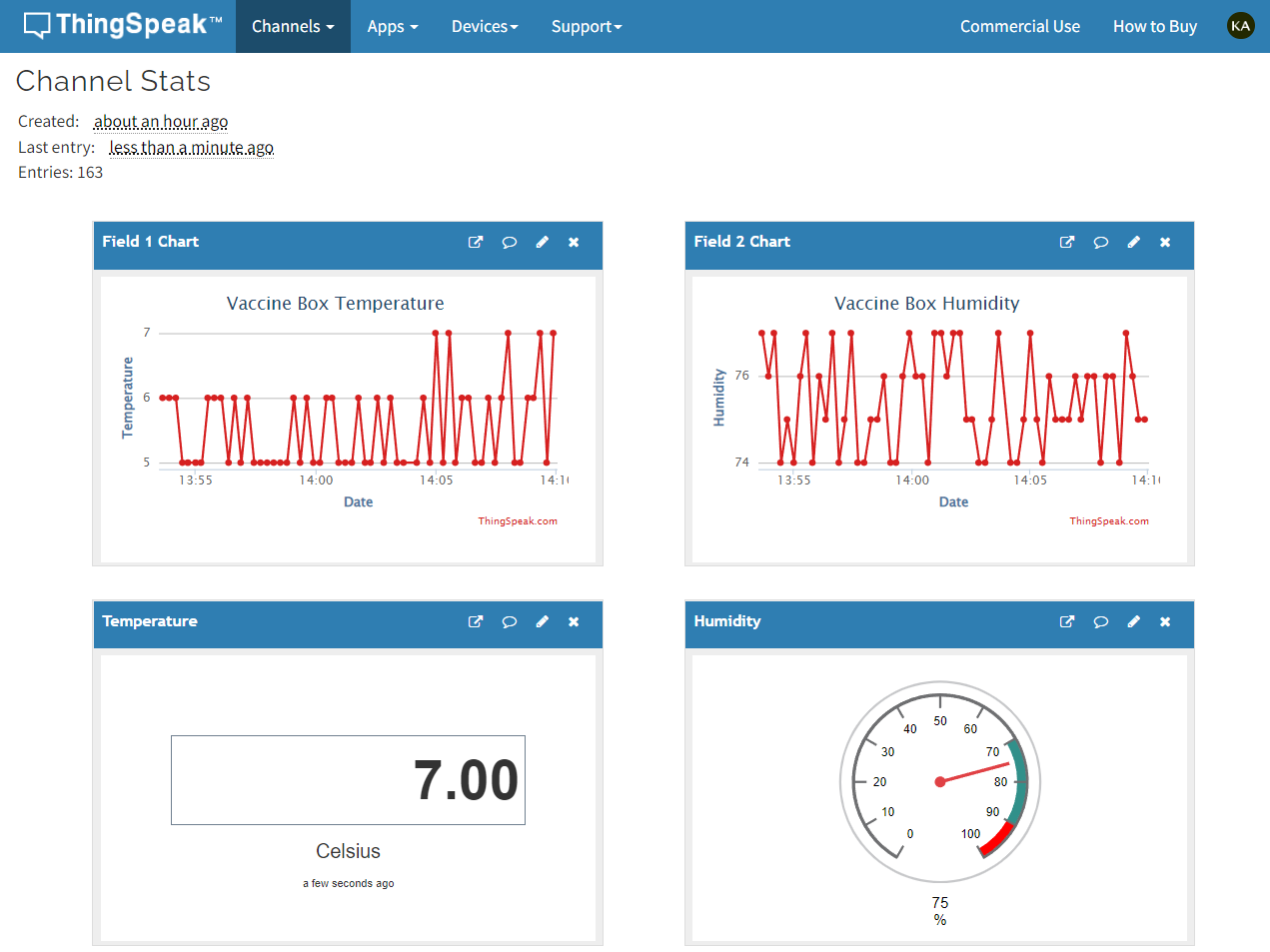
Possibly you know well about ThingSpeak. ThingSpeak is an IoT analytics platform service that allows you to aggregate, visualize, and analyze live data streams in the cloud. You can send data to ThingSpeak from your devices, create instant visualization of live data, and send alerts. We will use ThingSpeak to visualize our temperature and humidity data in a nice graphical dashboard.
At the heart of ThingSpeak is a ThingSpeak Channel. A channel is where you send your data to be stored. Each channel includes 8 fields for any type of data, 3 location fields, and 1 status field. Once you have a ThingSpeak Channel you can publish data to the channel, have ThingSpeak process the data, and then have your application retrieve the data.
To connect your device with the ThingSpeak you must have the API Key provided by the ThingSpeak. To configure the ThingSpeak & get the API key you can follow the following nice tutorial: https://microcontrollerslab.com/raspberry-pi-pico-dht22-dht11-thingspeak/. After getting the API key you need to place your own API key in the main code as shown in the red box in the image below.
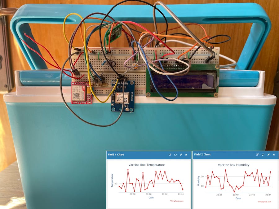
The following images show a demo setup of the hardware with the vaccine box.
ThingSpeak Dashboard


Comments
Please log in or sign up to comment.