It was several years back. I saw a video on television about HUMAN FOLLOWING SUITCASE. That time, I was astonished to see that type of amazing thing. At the same time, I was very inspired to make something like that in the future. My today's project is something like that. It's a human following robot and I am going to use very special and powerful hardware for my project. This is a KR260 Robotics Starter Kit from AMD. Thanks to AMD and Hackster for arranging the Pervasive AI Developer Contest and sending us this gorgeous hardware!!!
Let's start working...
Getting Started with KR260Every beginning is hard but it is not fully true for KR260 Robotics Starter Kit. Xilinx has some excellent online resources that make it easy for beginners.
The Kria-RoboticsAI GitHub repository is one of the good getting-started resources. This document explains how to start with the Kria KR260 Robotics Starter Kit. The kit has the following accessories inside the box:
- power supply and its adapters,
- Ethernet cable,
- USB A-male to micro B cable,
- a micro-SD card with an adapter, possibly with a size greater than 32GB
But to utilize the KR260 desktop environment you will be required the following accessories:
- USB Keyboard,
- USB Mouse,
- DisplayPort Cable (for connecting to a monitor),
- an HDTV (1920x1080 as minimum resolution) monitor with the DisplayPort connector.
But if you like to access the board remotely using SSH like PuTTY or Tera Term you are good to go with only the inbox accessories.
To get the real desktop feeling, we managed the above accessories with an additional webcam.
Following the guide mentioned above, we were able to successfully download the Ubuntu 22.04 LTS for AMD and wrote the image file to the SD card using Balena Etcher.
After connecting all the peripherals and powering up the KR260 with Ubuntu 22.04 GNOME Desktop was loaded successfully within a few seconds.
After login, we had a quick check of the internet connection using ifconfig
We used the following command to set the date before installing the necessary software (you may face problems accessing the internet without the correct date and time):
sudo date -s "YYYY-MM-DD HH:MM:SS"For installing the PYNQ DPU we followed Step 3 of the referred GitHub. The only problem we faced was the mismatch of names mentioned between the example commands and the GitHub repo.
Changing the name helped us to resolve the issue. For example, we changed the following commands:
#install dos2unix utility
sudo apt install dos2unix
# go to the scripts folder
cd /home/ubuntu/KR260-Robotics-AI-Challenge/files/scripts
# check each shell file
for file in $(find . -name "*.sh"); do
    echo ${file}
    dos2unix ${file}
done
with the following commands (only replace KR260-Robotics-AI-Challenge with Kria-RoboticsAI):
#install dos2unix utility
sudo apt install dos2unix
# go to the scripts folder
cd /home/ubuntu/Kria-RoboticsAI/files/scripts
# check each shell file
for file in $(find . -name "*.sh"); do
    echo ${file}
    dos2unix ${file}
done
We did the same for all the related commands. After installing the PYNQ we checked it using ls -l pynq-dpu command. We got a positive result.
After installing the PYNQ environment we installed the ROS2. For installing first we activated the pynq virtual environment using the following commands:
sudo su
source /etc/profile.d/pynq_venv.sh
Then we had to launch the install_ros.sh script from this repository to install ROS2 (also we did the previous changes here):
cd /home/ubuntu/
cd Kria-RoboticsAI/files/scripts/
source ./install_ros.sh
As ROS2 was installed, we verified it by starting TurtleSim by entering the following commands in the terminal:
# set up your ROS2 environment
source /opt/ros/humble/setup.bash
# launch the turtle simulator
ros2 run turtlesim turtlesim_node
Though we got an error message in the terminal the TurtleSim was run successfully.
Now we can say our developing environment is completely ready for developing custom applications. Before starting our own application we did some experiments with the Python sample notebook projects installed with PYNQ. Following are two example of our experiments.
The above experiments helped us to get a clear idea about the PYNQ environment and made us confident in writing our code.
Writing CodeWe planned to include Programmable Logic (FPGA) and ROS2 for developing code of our human following robot. For following any human the robot must detect the human. So, the robot must have a camera. We managed a Logitech HD webcam for this purpose. For detecting a person we used YOLOv3 on the VOC tf model. I downloaded the mode from the Xilinx Vitis-AI Model Zoo GitHub repository. (This repository is rich with many out-of-the-box model for KR260 Kit).
The model we downloaded was a ready-to-use object detection model compatible with Kria PYNQ DPU IP.
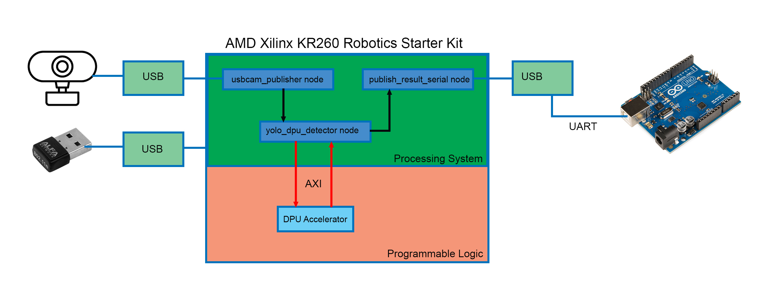
We used ROS2 for developing our code and divided the whole work into three separate Nodes.
- usbcam_publisher node: this node is responsible for taking image continuously from the webcam and publish to another node.
- yolo_dpu_detector node: this node receives images from the usbcam_publisher node and uses KR260 hardware accelerator (DPU IP) for detecting any person in the image using YOLO3 object detection model. If it detects any person, the information is published to another node.
- publish_result_serial node: this node receives the detection result from the previous node and sends the result to the Arduino board using USB serial.
We developed an optional node for taking an image and resizing the image using hardware accelerator (PL). If you need to resize the image you can use the cam_resizer_publisher node.
The following figure shows the program flow of our project.
The following qt graph image shows the data flow among nodes.
The full code is provided in our GitHub repository. The necessary commands list for developing ROS2 nodes is provided in the code section of this tutorial.
The following video shows how we ran and tested the developed code.
Making the RobotAfter finishing writing the code and testing we gave our full attention to building the robot hardware. Building hardware is hard and more than hard for building robots where you have to work with lots of motors and sensors. When you have several medium or high-power motors in your project, providing the required amount of power appears as a real challenge. Even sometimes you will get unstable behavior from your robot for not choosing the right size/type of wire. Making a bot from scratch involves lots of soldering and wiring works. Choosing a ready-made chassis can help to save a planty amount of time. As we already spent a lot of time on experimenting and developing code and the deadline is approaching soon, we selected a DFRobot Rover 5 tank chassis for our human follower project. We fixed an acrylic sheet on top of the chassis by using zip ties.
Then using some M3 screws and nuts we attached the motor driver board and Arduino board on top of the acrylic base as shown in the following image.
For adding and moving the web camera we screwed a 9g servo-based pan & tilt camera mount in the front side of the bot. The camera mount is capable of moving the camera both horizontally and vertically.
Finally, we placed the gorgeous KR260 Robotics Starter Kit on the back side of the bot.
We used screws and washers to tightly attach the KR260 board in the robot chassis. We added 3-cell LiPo battery with a zip tie.
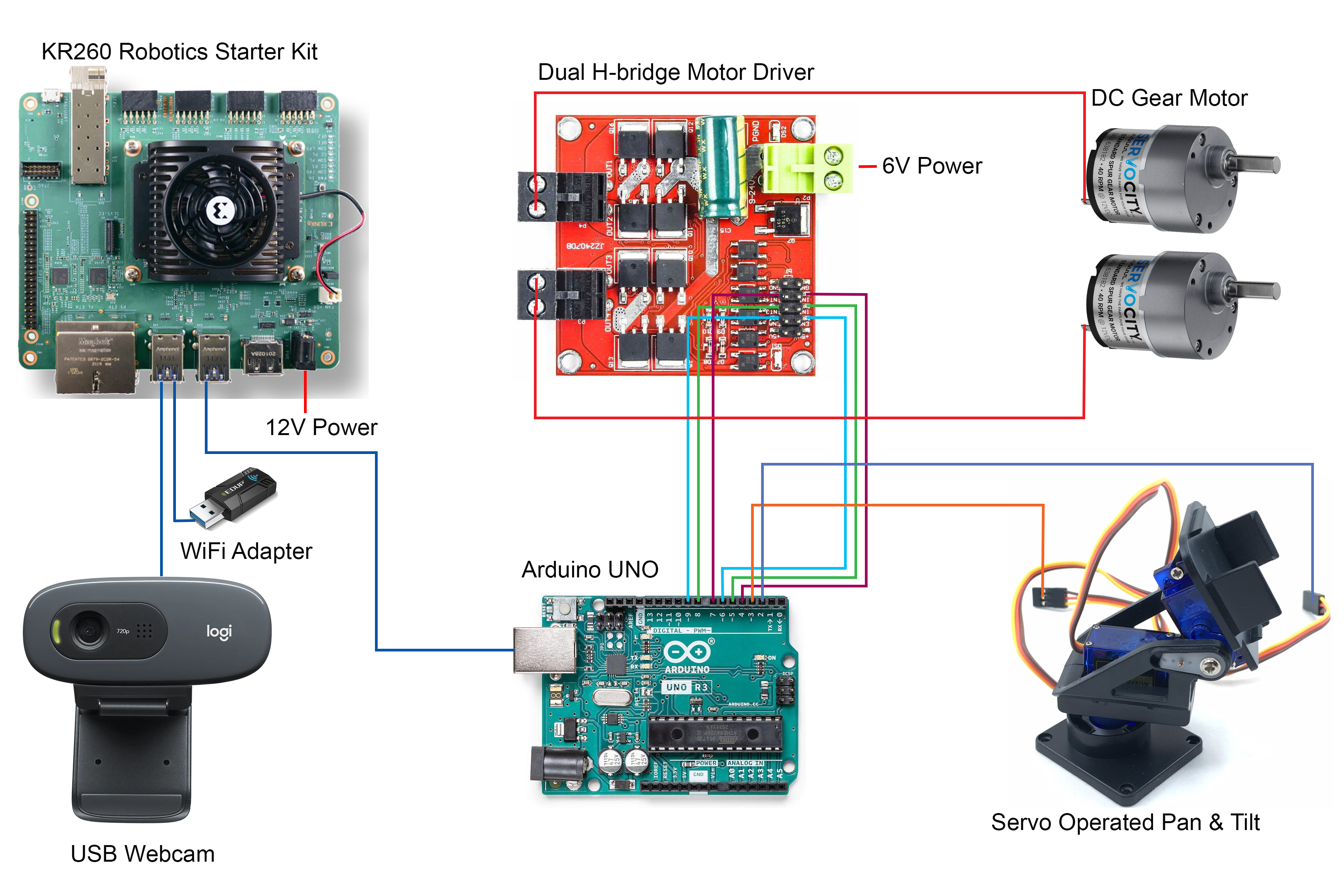
Arduino is connected to the Kr260 board with a USB cable. Arduino is getting power and data from the Kria board through this USB serial cable. The webcam is connected to the Kria board using another USB port. The finished robot is shown in the following image.
The hardware connections are shown in the following image. All the USB connections are shown by individual single wires. Power connections are marked with text rather than the power supply. Arduino UNO is getting power from the KR260 board.
Due to time limitations, we could not implement our full plan. The following work should be done on the project:
1. For controlling the motor driver and servo motor we used an external microcontroller unit (Arduino UNO), but these tasks can be easily performed from the KR260 by modifying dpu.bit overlay using Xilinx Vivado.
2. We used a simple webcam to take images and we are not getting any depth information. In the future LiDAR sensors can be added with the webcam or a depth camera may be used. The depth information may be used to control the speed of the robot.
3. A display may be added for getting real-time feedback from the robot.
I am very much passionate about robotics. I am seriously studying FPGA, ZYNQ, and ROS2. As my country is an agricultural country, I am very determined to build an autonomous agricultural robot (Farmio) that will be used to automatically detect and remove weeds, detect plant diseases from the image, and collect important soil parameters. In that case, I need to develop my own machine-learning model from the custom datasets. AMD Vitis AI can be a useful tool for that purpose. For bringing autonomous behaviors I will use ROS2 NAV2 platform. Undoubtedly, considering the price and performance KR260 Robotics Starter Kit will be the perfect brain for my future robot.
Few Resources:1. To get started using the KR260 Robotics Starter Kit for your application, please see: https://github.com/amd/Kria-RoboticsAI
2. For detailed information on PYNQ: PYNQ - Python productivity for Zynq - Home
3. For more information on the KR260 Starter Kit Applications: Kria KR260 Robotics Starter Kit Applications — Kria™ KR260 documentation (xilinx.github.io)
4. ROS2 documentation: Configuring environment — ROS 2 Documentation: Humble documentation


_ztBMuBhMHo.jpg?auto=compress%2Cformat&w=48&h=48&fit=fill&bg=ffffff)
_with_motor_driver_CzfrTN6n6e.jpg?auto=compress%2Cformat&w=48&h=48&fit=fill&bg=ffffff)


_3u05Tpwasz.png?auto=compress%2Cformat&w=40&h=40&fit=fillmax&bg=fff&dpr=2)
Comments
Please log in or sign up to comment.