'''
ELEC 424/553
Final Project
Authors: Eric Lin(el38), Shaun Lin(hl116), Yen-Yu Chien (yc185), Saif Khan (sbk7)
'''
# Import libraries
import time
import matplotlib.pyplot as plt
import numpy as np
import cv2
import math
from collections import Counter
from matplotlib.pyplot import savefig
# Code references from https://www.instructables.com/Autonomous-Lane-Keeping-Car-Using-Raspberry-Pi-and/
# Code references from https://www.hackster.io/covid-debuff/covid-debuff-semi-autonomous-rc-car-platform-75b072
# Many thanks to team COVID Debuff
# Convert the image to HSV format
def convert_to_HSV(frame):
hsv = cv2.cvtColor(frame, cv2.COLOR_BGR2HSV)
# cv2.imshow("HSV",hsv)
return hsv
# Detect the edges using canny method
def detect_edges(hsv):
# lower_blue = np.array([100, 43, 46], dtype = "uint8") # lower limit of blue color
# upper_blue = np.array([124, 255, 255], dtype="uint8") # upper limit of blue color
lower_blue = np.array([70, 90, 0], dtype="uint8") # lower limit of blue color
upper_blue = np.array([160, 255, 255], dtype="uint8") # upper limit of blue color
mask = cv2.inRange(hsv, lower_blue, upper_blue) # this mask will filter out everything but blue
# detect edges
edges = cv2.Canny(mask, 50, 200)
# cv2.imshow("edges",edges)
return edges
# Capture the bottom half of the image
def region_of_interest(edges, interest_area):
height, width = edges.shape # extract the height and width of the edges frame
mask = np.zeros_like(edges) # make an empty matrix with same dimensions of the edges frame
# only focus lower half of the screen
# specify the coordinates of 4 points (lower left, upper left, upper right, lower right)
polygon = np.array([[
(0, height),
(0, height * interest_area),
(width, height * interest_area),
(width, height),
]], np.int32)
cv2.fillPoly(mask, polygon, 255) # fill the polygon with blue color
cropped_edges = cv2.bitwise_and(edges, mask)
# cv2.imshow("roi",cropped_edges)
return cropped_edges
# Convert Envelopes to Regions
def detect_line_segments(cropped_edges):
rho = 1
theta = np.pi / 180
min_threshold = 15
line_segments = cv2.HoughLinesP(cropped_edges, rho, theta, min_threshold,
np.array([]), minLineLength=5, maxLineGap=50) #maxLineGap change from 0 to 50
return line_segments
# Slope calculation
def average_slope_intercept(frame, line_segments, interest_area): #line segments stores HoughLines
lane_lines = []
if line_segments is None:
# print("no line segment detected")
return lane_lines
height, width, _ = frame.shape
left_fit = []
right_fit = []
boundary = 1 / 3
#boundary = 1 / 2
left_average = 0
right_average = 0
left_cnt = 0
right_cnt = 0
left_region_boundary = width * (1 - boundary) # set boundary in x-axis
right_region_boundary = width * boundary
for line_segment in line_segments:
for x1, y1, x2, y2 in line_segment:
if x1 == x2:
# print("sKi_stpping vertical lines (slope = infinity)")
continue
fit = np.polyfit((x1, x2), (y1, y2), 1)
slope = (y2 - y1) / (x2 - x1)
intercept = y1 - (slope * x1)
if slope < 0:
right_average = right_average + slope
right_cnt = right_cnt + 1
if x1 < left_region_boundary and x2 < left_region_boundary:
left_fit.append((slope, intercept))
else:
left_average = left_average + slope
left_cnt = left_cnt + 1
if x1 > right_region_boundary and x2 > right_region_boundary:
right_fit.append((slope, intercept))
left_fit_average = np.average(left_fit, axis=0)
if len(left_fit) > 0:
lane_lines.append(make_points(frame, left_fit_average, interest_area))
right_fit_average = np.average(right_fit, axis=0)
if len(right_fit) > 0:
lane_lines.append(make_points(frame, right_fit_average, interest_area)) # make_points is defined in the next function
# lane_lines is a 2-D array consisting the coordinates of the right and left lane lines
# for example: lane_lines = [[x1,y1,x2,y2],[x1,y1,x2,y2]]
# where the left array is for left lane and the right array is for right lane
# all coordinate points are in pixels
return lane_lines
# Draw lines
def make_points(frame, line, interest_area):
height, width, _ = frame.shape
slope, intercept = line
y1 = height # bottom of the frame
y2 = int(y1 * (interest_area)) # make points from middle of the frame down
if slope == 0:
slope = 0.1
x1 = int((y1 - intercept) / slope)
x2 = int((y2 - intercept) / slope)
return [[x1, y1, x2, y2]]
# Display lines
def display_lines(frame, lines, line_color=(0, 255, 0), line_width=6): # line color (B,G,R)
line_image = np.zeros_like(frame)
if lines is not None:
for line in lines:
for x1, y1, x2, y2 in line:
cv2.line(line_image, (x1, y1), (x2, y2), line_color, line_width)
line_image = cv2.addWeighted(frame, 0.8, line_image, 1, 1)
return line_image
history_direction = 0
# Calculate the steering angles
def get_steering_angle(frame, lane_lines):
height, width, _ = frame.shape
if len(lane_lines) == 2: # if two lane lines are detected
_, _, left_x2, _ = lane_lines[0][0] # extract left x2 from lane_lines array # x2 is in the upper side of the camera
_, _, right_x2, _ = lane_lines[1][0] # extract right x2 from lane_lines array
mid = int(width / 2)
x_offset = (left_x2 + right_x2) / 2 - mid # the offset is the offset the original middle line
y_offset = int(height / 2)
elif len(lane_lines) == 1: # if only one line is detected
x1, _, x2, _ = lane_lines[0][0] # extract the x1 and x2 from the only line
if(x1 > 80):
history_direction = 2
elif(x1 < 80):
history_direction = 1
else:
history_direction = 0
x_offset = x2 - x1
y_offset = int(height / 2)
elif len(lane_lines) == 0: # if no line is detected
x_offset = 0
y_offset = int(height / 2)
angle_to_mid_radian = math.atan(x_offset / y_offset) # use the offset to calculate the offset radian from the original middle line
angle_to_mid_deg = int(angle_to_mid_radian * 180.0 / math.pi)
steering_angle = angle_to_mid_deg + 90
return steering_angle
# Draw the heading line
def display_heading_line(frame, steering_angle, interest_area, line_color=(0, 0, 255), line_width=5):
heading_image = np.zeros_like(frame)
height, width, _ = frame.shape
steering_angle_radian = steering_angle / 180.0 * math.pi # steeting_angle is by degree, so now to transfer
x1 = int(width / 2)
y1 = height
x2 = int(x1 - height / 2 / math.tan(steering_angle_radian)) # = (x1 - (height/2)/tangent )
y2 = int(height * interest_area)
cv2.line(heading_image, (x1, y1), (x2, y2), line_color, line_width)
heading_image = cv2.addWeighted(frame, 0.8, heading_image, 1, 1)
return heading_image
#======================================= 20231201 ===========================================
# Set the period time of the PWM
period_time = 20000000
def init_ESC():
with open('/dev/bone/pwm/1/a/period', 'w') as filetowrite:
filetowrite.write(str(period_time))
with open('/dev/bone/pwm/1/a/enable', 'w') as filetowrite:
filetowrite.write('1')
with open('/dev/bone/pwm/1/b/period', 'w') as filetowrite:
filetowrite.write(str(period_time))
with open('/dev/bone/pwm/1/b/enable', 'w') as filetowrite:
filetowrite.write('1')
return
# Modify the speed of the motor
def modify_Motor(percentage):
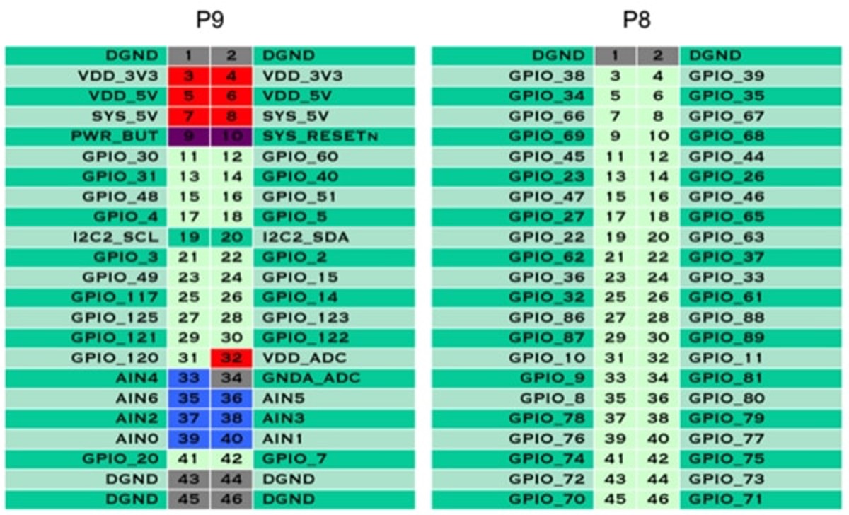
# P9_14 - Speed/ESC
with open('/dev/bone/pwm/1/a/duty_cycle', 'w') as filetowrite:
filetowrite.write(str(int(percentage / 100 * period_time)))
return
# Modify the steering angle of the servo
def modify_Servo(percentage):
# P9_16 - Steering
with open('/dev/bone/pwm/1/b/duty_cycle', 'w') as filetowrite:
filetowrite.write(str(int(percentage / 100 * period_time)))
return
# Detect the red edges for red box detection
def detect_red_edges(frame):
# lower_blue = np.array([150, 30, 30], dtype="uint8") # lower limit of red color
# upper_blue = np.array([180, 255, 255], dtype="uint8") # upper limit of red color
lower_blue = np.array([0, 30, 166], dtype="uint8") # lower limit of pink color
upper_blue = np.array([179, 68, 246], dtype="uint8") # upper limit of pink color
mask = cv2.inRange(frame, lower_blue, upper_blue) # this mask will filter out everything but red
return mask
def findPen(img, imgContour):
hsv = cv2.cvtColor(img, cv2.COLOR_BGR2HSV)
lower = np.array([119, 4, 127], dtype="uint8")
upper = np.array([179, 218, 255], dtype="uint8")
mask = cv2.inRange(hsv, lower, upper)
result = cv2.bitwise_and(img, img, mask=mask) #return cropped_edges : in the yufi's code
penx, peny = findContour(mask, imgContour)
cv2.circle(img, (penx, peny), 10, [0, 0, 255], cv2.FILLED)
# print("x=", penx)
# print("y=", peny)
# if peny!=-1:
# #drawPoints.append([penx, peny, i])
# # drawPoints.append([penx, peny])
# #==============
# print("x=",penx)
# print("y=",peny)
return penx, peny
def findContour(img, imgContour):
contours, hierarchy = cv2.findContours(img, cv2.RETR_EXTERNAL, cv2.CHAIN_APPROX_NONE)
x, y, w, h = -1, -1, -1, -1
for cnt in contours:
cv2.drawContours(imgContour, cnt, -1, (0, 0, 255), 4)
area = cv2.contourArea(cnt)
if area > 2500: # original area > 500
peri = cv2.arcLength(cnt, True)
vertices = cv2.approxPolyDP(cnt, peri * 0.02, True)
x, y, w, h = cv2.boundingRect(vertices)
return x+w//2, y
T = []
steer_error = []
speed_error = []
steer_P = []
steer_I = []
steer_D = []
speed = []
steer_pwm_duty = []
speed_pwm_duty = []
# PID control loop (to be called for each frame or time interval)
def pid_control(frame_number, current_steering_angle, desired_steering_angle, min_steering_angle, max_steering_angle):
# Initialize variables for PID
integral_error = 0
last_error = 0
last_time = None
# PID parameters
Kp_st = 0.3395 # Proportional gain
Ki_st = 0.0973 # Integral gain
Kd_st = 0.0818 # Derivative gain
# Calculate time difference
current_time = time.time()
time_difference = current_time - last_time if last_time is not None else 1
last_time = current_time
# Error between the desired and actual steering angle
error = desired_steering_angle - current_steering_angle
# Integral error (sum over time)
integral_error += error * time_difference
# Derivative error (rate of change of error)
derivative_error = (error - last_error) / time_difference
last_error = error
# Compute new steering angle or control output
pid_output = Kp_st * error + Ki_st * integral_error + Kd_st * derivative_error
global T, steer_error, steer_P, steer_I, steer_D
T = np.append(T, [frame_number])
steer_error = np.append(steer_error, [error / 100])
steer_P = np.append(steer_P, [Kp_st * error])
steer_I = np.append(steer_I, [Ki_st * integral_error])
steer_D = np.append(steer_D, [Kd_st * derivative_error])
# Adjust with neutral steering angle (90 degrees)
new_steering_angle = pid_output + 90
# Apply bounds to the steering angle if necessary
new_steering_angle = max(min_steering_angle, min(new_steering_angle, max_steering_angle))
return new_steering_angle
def map_angle_to_duty_cycle(new_steering_angle, min_angle, max_angle, min_duty_cycle, max_duty_cycle, neutral_duty_cycle):
neutral_angle = 90
# Calculate the range of steering motion and corresponding duty cycle range
left_angle_range = neutral_angle - min_angle
right_angle_range = max_angle - neutral_angle
left_duty_cycle_range = max_duty_cycle - neutral_duty_cycle
right_duty_cycle_range = neutral_duty_cycle - min_duty_cycle
# Map the steering angle to duty cycle
if new_steering_angle < neutral_angle: # Turning left
duty_cycle = ((neutral_angle - new_steering_angle) / left_angle_range) * left_duty_cycle_range + neutral_duty_cycle
else: # Turning right
duty_cycle = neutral_duty_cycle - ((new_steering_angle - neutral_angle) / right_angle_range) * right_duty_cycle_range
return duty_cycle
def init_Setup():
# Initialize ESCs
init_ESC()
# Initialize the servo and motor
intial_percentage = 7.5
modify_Servo(intial_percentage)
modify_Motor(intial_percentage)
time.sleep(0.5)
def main():
# Initialize the ESC
init_Setup()
# Start the motor
new_battery = True
if new_battery:
slow_speed_percentage = 8.015
fast_speed_percentage = 8.009
else:
slow_speed_percentage = 8.400
fast_speed_percentage = 8.500
speed_percentage = fast_speed_percentage
# Initialize the camera
video = cv2.VideoCapture(2)
# Set the resolution of the camera
video.set(cv2.CAP_PROP_FRAME_WIDTH, 160)
video.set(cv2.CAP_PROP_FRAME_HEIGHT, 120)
# History variable
current_steering_angle = 90
# Red boxes detect & count
red_y = -1
red_cnt = 0
# interest area
interest_area = 4/10 # mask upper 1/3 area
# Records for graphs
frame_number = 0
# Sign variables
end_flag = 0
target_speed = 4e-07
detect_done_flag = False
update_frame = 0
second_area_flag = False
headers = ["Current Angle", "Desired Angle", "New Angle", "Servo %", "Speed %"]
# Format the data
formatted_data = "| {:<15} | {:<15} | {:<15} | {:<10} | {:<10} |".format(
"Current Angle", "Desired Angle", "New Angle", "Servo %", "Speed %"
)
print(formatted_data)
# Stop loop when ctrl+c
try:
while True:
# Read from camera
ret, frame = video.read()
if frame is None:
print("Error: Unable to load the image.")
# Make a copy of the frame
imgContour = frame.copy()
# print the current frame number
frames_num = video.get(cv2.CAP_PROP_POS_FRAMES)
# Process the images
hsv = convert_to_HSV(frame)
edges = detect_edges(hsv)
red_edges = detect_red_edges(hsv)
# TEST
if current_steering_angle > 110 or current_steering_angle < 70:
interest_area = 5/10
else:
interest_area = 4/10
# print(interest_area)
red_edges = region_of_interest(red_edges, interest_area)
# Red boxes detection
red_x, red_y = findPen(frame, imgContour)
# If the red box is detected
if red_y!=-1 and not detect_done_flag:
print("Detected")
if second_area_flag:
time.sleep(0.6)
modify_Motor(7.5)
time.sleep(5)
modify_Motor(10.0)
detect_done_flag = True
second_area_flag = True
update_frame = frame_number
slow_speed_percentage = 8.02
fast_speed_percentage = 8.04
# Wait for 50 frames to reset the flag
frame_diff = frame_number - update_frame
if frame_diff > 50:
detect_done_flag = False
# print("Flag:", detect_done_flag)
# Detect the lane lines
line_segments = detect_line_segments(edges)
lane_lines = average_slope_intercept(frame, line_segments, interest_area)
lane_lines_image = display_lines(frame, lane_lines)
desired_steering_angle = get_steering_angle(frame, lane_lines)
heading_image = display_heading_line(lane_lines_image, desired_steering_angle, interest_area)
key = cv2.waitKey(10)
cv2.imwrite('/home/debian/Group4/src/opencv/frames/snap%s.png' % frames_num, heading_image)
# ===================== STEER PID =====================
new_steering_angle = pid_control(frame_number, current_steering_angle, desired_steering_angle, 60, 120)
servo_percentage = map_angle_to_duty_cycle(new_steering_angle, 60, 120, 3.5, 10.5, 7.5)
# print(round(current_steering_angle,2), round(desired_steering_angle,2), round(new_steering_angle,2), round(servo_percentage,2))
# modify the PWM duty of servo
modify_Servo(servo_percentage)
current_steering_angle = new_steering_angle
# ==================== SPEED PID =====================
# Check the angle, if the angle is too large, slow down the car
integral_bound = 5
if (servo_percentage >= 8.8 and frame_number % integral_bound == 0):
speed_percentage = slow_speed_percentage
elif (servo_percentage <= 6.3 and frame_number % integral_bound == 0):
speed_percentage = slow_speed_percentage
else:
speed_percentage = fast_speed_percentage
# Modify the PWM duty of motor
modify_Motor(speed_percentage)
# Format the data
# formatted_data = "| {:<15} | {:<15} | {:<15} | {:<10} | {:<10} |".format(
# "Current Angle", "Desired Angle", "New Angle", "Servo %", "Speed %"
# )
formatted_data = "| {:<15} | {:<15} | {:<15} | {:<10} | {:<10} |".format(
round(current_steering_angle, 2),
round(desired_steering_angle, 2),
round(new_steering_angle, 2),
round(servo_percentage, 2),
round(speed_percentage, 2),
)
print(formatted_data)
# Show the image
# cv2.imshow('original', heading_image)
key = cv2.waitKey(10)
# save each frame to a png to make a video '/home/debian/Group4/src/opencv/frames/snap%s.png'
cv2.imwrite('/home/debian/Group4/src/opencv/frames/snap%s.png' % frames_num, heading_image)
global steer_pwm_duty, speed_pwm_duty
steer_pwm_duty = np.append(steer_pwm_duty, [servo_percentage])
speed_pwm_duty = np.append(speed_pwm_duty, [speed_percentage])
frame_number = frame_number + 1
except KeyboardInterrupt:
modify_Motor(7.5)
pass
def plot_graph():
global T, steer_error, steer_P, steer_I, steer_D, speed_pwm_duty, steer_pwm_duty
# Plot the first graph
plt.figure()
plt.plot(T, steer_error, color='orange', linewidth=1.0, linestyle='solid', label='Error')
plt.plot(T, steer_P, color='red', linewidth=1.0, linestyle='solid', label='Proportional Response')
plt.plot(T, steer_I, color='blue', linewidth=1.0, linestyle='solid', label='Derivative Response')
plt.plot(T, steer_D, color='green', linewidth=1.0, linestyle='solid', label='Integral Response')
plt.legend(loc='upper right')
plt.title('PID Responses vs. Frame Number')
plt.xlabel('Frame')
plt.ylabel('PID Responses')
plt.grid()
# Plot the second graph
plt.figure()
# plt.plot(T, speed_error, color='red', linewidth=1.0, linestyle='solid', label='Speed Error')
plt.plot(T, steer_error, color='orange', linewidth=1.0, linestyle='solid', label='Steer Error')
plt.plot(T, speed_pwm_duty, color='blue', linewidth=1.0, linestyle='solid', label='Speed PWM')
plt.plot(T, steer_pwm_duty, color='green', linewidth=1.0, linestyle='solid', label='Steer PWM')
plt.legend(loc='upper right')
plt.title('PWM and Error vs. Frame Number')
plt.xlabel('Frame')
plt.ylabel('Values')
plt.ylim((0, 11.5))
plt.grid()
# # Do the plot
# plt.show()
# Save the plots to files
savefig('plot1.png')
main()
plot_graph()


Comments
Please log in or sign up to comment.