


Hardware components | ||||||
 |
| × | 1 | |||
| × | 1 | ||||
Software apps and online services | ||||||
 |
| |||||
Hand tools and fabrication machines | ||||||
 |
| |||||
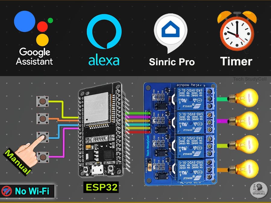
In this ESP32 project, I have shown how to make an IoT-based Home Automation with Google Assistant & Alexa using ESP32 to control 3 home appliances with voice commands.
During the article, I have shown all the steps to make this smart home system.
If the internet is unavailable, you can control the home appliances from manual switches.
Tutorial Video on this ESP32 IoT ProjectThis complete Home Automation system has the following features:
- Control appliances with Google Assistant
- Control appliances with Alexa
- Control appliances manually with switches.
- Monitor real-time feedback in the Google Home and Amazon Alexa App.
- You can also set Automation to control the relays automatically.
- Control home appliances manually without internet.
- For this project, I have used a FREE Sinric Pro account
So, you can easily make this home automation project at home just by using an ESP32 and relay module. You can also use a custom-designed PCB for this project.
Required Components:1. ESP32 DEVKIT V1
2. 4-channel SPDT 5V Relay Module
3. Manual Switches or Push Buttons
4. Alexa Echo Dot (Optional)
If you use the custom-designed PCB for this project, then please refer to the following required components list.
Required Components for the PCB- ESP32 DEVKIT V1
- Relays 5v (SPDT) (4 no)
- BC547 Transistors (4 no)
- PC817 Optocuplors (4 no)
- 510-ohm 0.25-watt Resistor (4 no) (R1 - R4)
- 1k 0.25-watt Resistors (6 no) (R5 - R10)
- 10k 0.25-watt Resistor (1 no) (R11)
- LED 5-mm (6 no)
- 1N4007 Diodes (4 no) (D1 - D4)
- Push Buttons (4 no)
- Terminal Connectors
- 5V DC supply
1. Arduino IDE
2. Google Home App
3. Amazon Alexa App
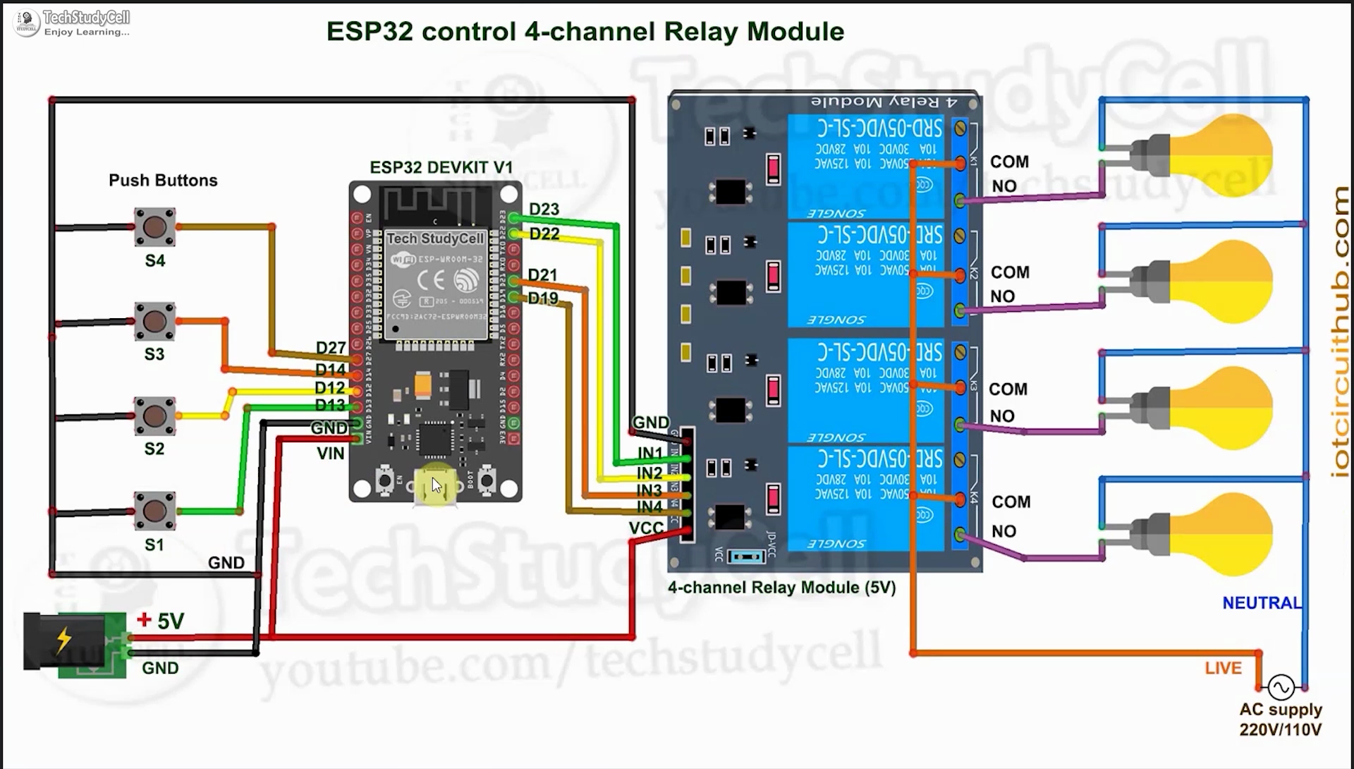
Circuit Diagram of the ESP32 Home Automation ProjectThe circuit is very simple, I have used the GPIO pins D23, D22, D21 & D19 to control the 4 relays.
And, the GPIO pins D13, D12, D14 & D27 are connected with switches to control the 4 relays manually.
I have used the INPUT_PULLUP function in Arduino IDE instead of using the pull-up resistors.
I have used a 5V mobile charger to supply the smart relay module.
Please take proper safety precautions while working with high voltage.
Control Relays With Google Assistant Using ESP32If the ESP32 is connected to the WiFi, then you can control the home appliances from the Google Home App and also from the push buttons / manual switches.
You can also tell Google Assistant to turn on or off the appliances.
Plus, you can check and control relay status from anywhere using the Google Home App, without needing a Google Home Nest device.
Control Relays With Alexa Using ESP32You can also control the home appliances from the Amazon Alexa App if the ESP32 is connected to the WiFi.
You can also tell Alexa to turn on or off the appliances.
You can also control the appliances from the push buttons / manual switches, Plus monitors the real-time feedback of the relays in the Amazon Alexa App from anywhere in the world.
You don't need any Echo devices for this IoT project.
Controlling Relays Manually With Pushbuttons / SwitchesIf the WiFi is disconnected, you can control the relays from the push buttons / manual switches.
The ESP32 will check for the WiFi after every 5 seconds. When the WiFi is available, the ESP32 will automatically connect with the WiFi.
Please refer to the circuit diagram to connect the manual switches.
Design the PCB for This ESP32 ProjectTo make the circuit compact and give it a professional look, I designed the PCB after testing all the features of the smart relay module.
You can download the PCB Gerber, BOM, and "pick and place" files of this ESP32 control relay PCB from the following link:
GitHub link to Download PCB Gerber File (for SMT)
GitHub link to Download through hole PCB Gerber file.
For this project, I have the JLC SMT Service while ordering the PCB.
On JLCPCB's one-stop online platform, customers enjoy low-cost & high-quality & fast SMT service at an $8.00 setup fee($0.0017 per joint).
$27 New User coupon & $24 SMT coupons every month.
Visit https://jlcpcb.com
JLCPCB SMT Parts Library 200k+ in-stock components (689 Basic components and 200k+ Extended components)
Parts Pre-Order service https://support.jlcpcb.com/article/164-what-is-jlcpcb-parts-pre-order-service
Build a Personal library Inventory, save parts for now or the future
Assembly will support 10M+ parts from Digikey, Mouser.
Steps to Order the PCB Assembly from JLCPCB1. Visit https://jlcpcb.com and Sign in / Sign up.
2. Click on the QUOTE NOW button.
3. Click on the "Add your Gerber file" button. Then browse and select the Gerber file you have downloaded.
4. Set the required parameters like Quantity, PCB masking color, etc.
5. Select the Assemble side and SMT Quantity.
6. Now upload the BOM and PickAndPlace files.
7. Now confirm all the components which you want to be soldered by SMT services.
8. Click on the SAVE TO CART button.
Select Shipping Address and Payment Mode6. Type the Shipping Address.
7. Select the Shipping Method suitable for you.
8. Submit the order and proceed with the payment.
You can also track your order from the JLCPCB
My PCBs took 3 days to get manufactured and arrived within a week using the DHL delivery option.
PCBs were well-packed and the quality was really good at this affordable price.
First, visit https://sinric.pro/
You have to create an account in Snric Pro.
Then log in to the Sinric Pro Account.
You will get an APP KEY and APP SECRET for the account, which will be required in the code.
Add Room in Sinric Pro accountAfter that add a room and give a nickname to that room (Ex: Living Room)
Add Devices to Sinric Pro accountThen Add devices one by one and give the nickname for each device. Sinric will assign a unique device ID for each device.
Here, I have used the free Sinric Pro account, so I can add a maximum of 3 devices for free.
Generate the Code Using ZeroCode FeaturesNow you can generate the source code using the Sinric Zero Code features.
- Click on the Zero Code.
- Select the Devices and Switch type
- Enter the GPIO details for Relays and switches
- Enter WiFi name and password
- Click on Download.
Please refer to the tutorial video.
Program ESP32 Using Arduino IDEFirst, download the code & install all the required libraries mentioned in the code.
Required Libraries:
- Sinric Pro
- ArduinoJson
- WebSockets
After that select the DOIT ESP32 DEVKIT V1 board and the PORT.
Then click on the upload button.
Setup the Google Home AppFirst, download and install the Google Home App. then follow the steps to create Home in Google Home app
- Tap on the "+" icon (upper left corner).
- Tap on Create new home.
- Enter the Home nickname and address.
- Then click on Continue.
The Home is created. Now again tap on the "+" icon to add devices.
Connect Sinric Pro With Google Home App | Add DevicesAfter creating the Home in the Google Home app, you can connect the Sinric Pro with the Google Home app
- Tap on the "+" icon, then select Set up device.
- Tap on Works with Google.
- Search for Sinric Pro, then select Sinric Pro.
- Enter the email id and password used for the Sinric account,
- Then tap on Sign in.
Thus, all the devices from Sinric Pro will be added to Google Home Account.
Configure the Alexa App for This Smart Home SystemDownload and install the Amazon Alexa App from the Google play store or App Store.
- Go to "More", then select "Skills & Games"
- Search for Sinric Pro and tap on "Sinric Pro".
- Tap on "ENABLE TO USE"
- Log in with the Sinric account credentials.
- Tap on CLOSE.
- Tap on "DISCOVER DEVICES".
- It will take a minute to add devices. During this time the ESP32 should be connected with the WiFi.
- Tap on "Devices", and tap on "Plug" to see all the devices.
Thus, all the devices from Sinric Pro will be added to the Amazon Alexa App.
Test the ESP32 ProjectBefore connecting the appliances test the circuit.
Finally!! the IoT-based Smart Home System Is ReadyNow you can smartly control your home appliances.
I hope you have liked this Google and Alexa control home automation project. I have shared all the required information for this project.
I would appreciate it if you share your valuable feedback. Also if you have any queries please write in the comment section.
Thank you & Happy Learning.


Comments
Please log in or sign up to comment.