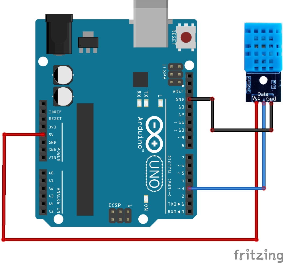
- Connect Vcc Pin of T&H sensor to 5V on Arduino
- Connect GND Pin of T&H sensor to GND on Arduino
- Connect Data Pin of T&H sensor to D3 on Arduino
Note: The DHT11 Module has only 3 pins. In case you only have the DHT11 sensor and not the module, you'll notice it has 4 pins. They are as follows: Vcc, Data, NC, GND. Leave the connection for NC pin empty and connect a resistor of 5-10k between the Vcc and Data pin of the sensor. Connect the rest as mentioned above in points. Refer to Circuit diagram for more understanding.
Download the DHT sensor library and add this ZIP file in Include Library under Sketch in Arduino IDE.
WorkingAs the name suggests, the sensor is used to measure Temperature and Humidity. Humidity is the amount of water vapour in the air. Higher the amount of water vapour in air, higher the humidity.
By asking Google and referring to few webpages, I have come to an understanding that- the sensor is classified into Relative humidity sensor and Absolute humidity sensor based on the type of humidity. Measuring parameters further classifies this sensor as Capacitive humidity sensor, Resistive humidity sensor etc.,
Deep understanding of sensor and it's working is not necessary to complete this project. We are trying to keep this project very basic. We really encourage curious minds to explore more and we'd appreciate if you could share your knowledge in the comments below.
Now, let us see the circuit we put together


_ztBMuBhMHo.jpg?auto=compress%2Cformat&w=48&h=48&fit=fill&bg=ffffff)


Comments
Please log in or sign up to comment.