The mouse and keyboard are two essential input devices used for computing. Wireless keyboards and mice have become increasingly popular due to their convenience and freedom from cables. Instead of relying on physical connections, they use wireless technologies such as Bluetooth or radio frequency (RF) to communicate with the computer.
Wireless keyboards and mice offer several benefits. They provide greater flexibility, allowing users to move and position themselves more comfortably without the constraint of cables. This can be particularly useful in scenarios such as presentations or when using a computer from a distance.
To ensure reliable wireless communication, these devices typically come with a receiver that plugs into the computer's USB port. The keyboard or mouse connects wirelessly to the receiver, establishing a secure and stable connection.
Overall, the integration of wireless functionality in keyboards and mice has greatly enhanced user experience, providing greater freedom of movement and flexibility in various computing scenarios.
EXISTING SYSTEM vs CURRENT SYSTEMTraditional mice and keyboards lack hardware-level customization options, often requiring users to rely on third-party software for customization purposes.
The Macro mouse, seamlessly integrate mouse and keyboard, customization, and gesture capabilities, are rare or highly expensive. This scarcity restricts users from experiencing the full potential of a unified device that combines these functionalities.
Universal control is another aspect where traditional mice and keyboards fall short. They offer limited support and lack the ability to work universally across various devices. In contrast, the macro mouse operates at the hardware level, enabling users to program it for use with any device, including embedded applications like drones or rovers. This means macro mouse could be used on various devices like phone or laptop seamlessly.
Battery life is a crucial consideration for wireless devices. Traditional wireless mice and keyboards often suffer from short battery life, requiring frequent recharging and negatively impacting the user experience. In contrast, the macro mouse boasts a massive 1500 mAh battery, providing extended usage time and enhancing overall satisfaction.
Latency is another area where traditional mice may lack configurability. However, the macro mouse can be tailored to work with high or low latency settings, allowing users to strike a balance between conserving battery life and optimizing the user experience. With its substantial battery capacity, the macro mouse defaults to a state of high throughput or low latency, contributing to an enhanced user experience.
The macro mouse offers unparalleled flexibility through its use of angular displacement. Users can control the mouse without physically moving it, as the device tracks the angles of movement. Additionally, users can configure the mouse to move at varying speeds corresponding to different angles, providing a customized and adaptable user experience.
Macro in macro mouse stands for customizability and flexibility.
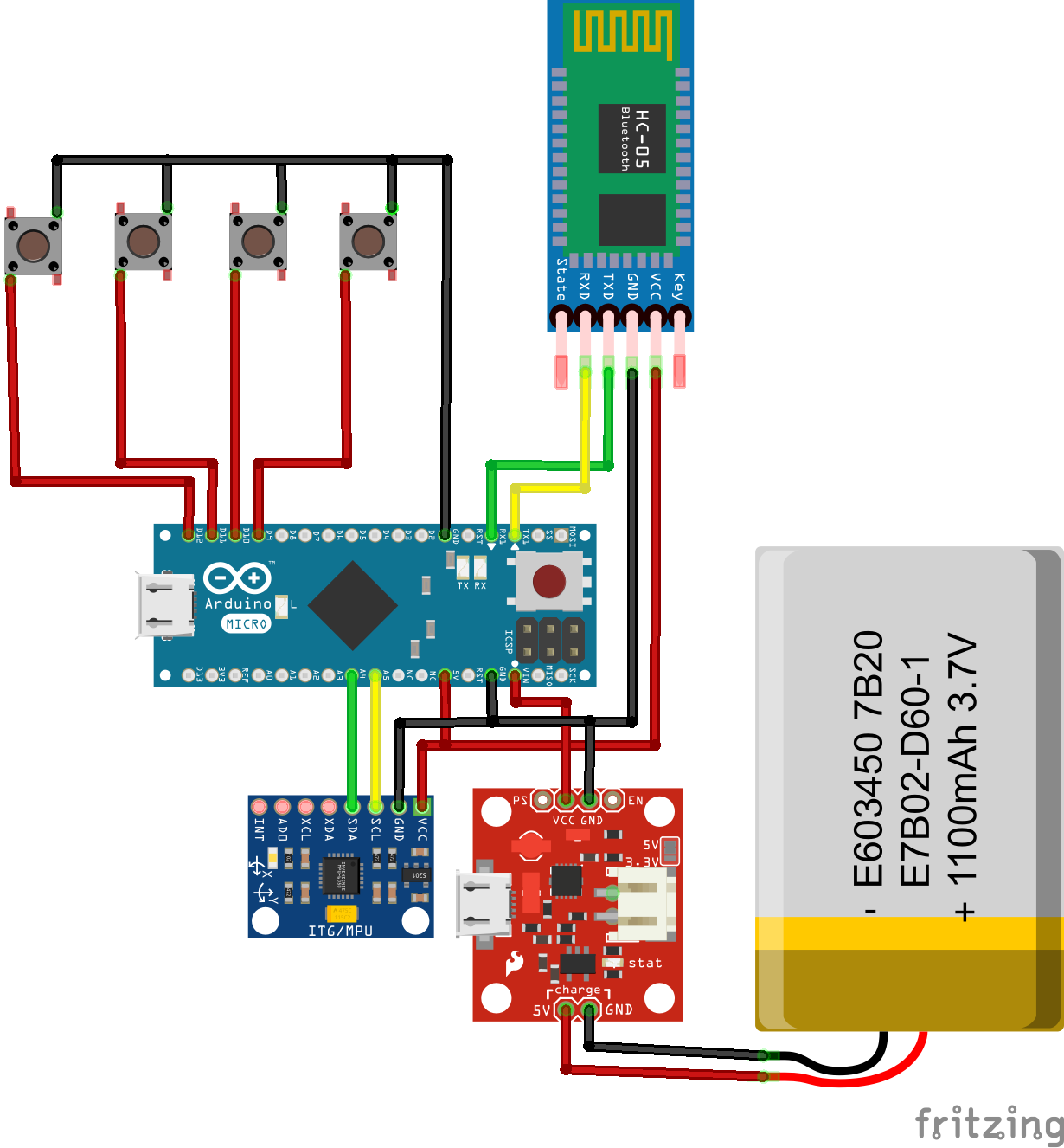
HARDWARE OVERVIEWTo send the mouse and keyboard commands to a host computer the best protocol is the USB protocol, as it is universally accepted by most devices (including your phone).Arduino pro micro is a microcontroller having the capability of acting as USB device. Hence it can be used as a USB receiver. HC05 Bluetooth module is a generic Bluetooth module, easy to use and implement for data transfer via the Bluetooth. TP4056 is a Battery management module for charging and discharging.MPU6050 is a gyroscope that is used to capture the movement of the hand.
4 mechanical switches are used instead of the tactile switches, as the mechanical switches provide customizable clickness. Additionally more switches could be added to the circuit in the similar fashion for additional functionality.
Additionally USB to micro USB converter could be attached with the Arduino pro mini such that it could be attached to any host easily.
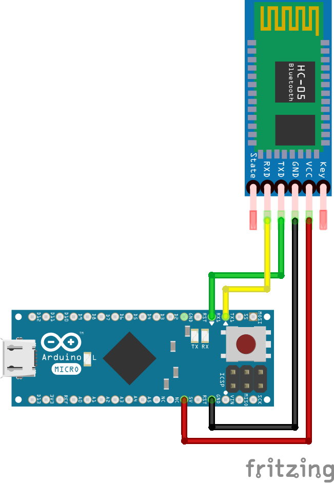
BLUETOOTH AUTO PAIRINGSo the RX pin of the Arduino needs to be connected to the RX pin of the Bluetooth module, and the TX pin of the Arduino to the TX pin of the Bluetooth module. Now while holding the small button over the “EN” pin we need to power the module and that’s how we will enter the command mode. If the Bluetooth module led is flashing every 2 seconds that means that we have successfully entered in the AT command mode.
After this we need to upload an empty sketch to the Arduino but don’t forget to disconnect the RX and TX lines while uploading. Then we need to run the Serial Monitor and there select “Both NL and CR”, as well as, “38400 baud” rate which is the default baud rate of the Bluetooth module. Now we are ready to send commands and their format is as following.
All commands start with “AT”, followed by the “+” sign, then a <Parameter Name> and they end either with the “?” sign which returns the current value of the parameter or the “=” sign when we want to enter a new value for that parameter.
Slave Configuration
So for example, if we type just “AT” which is a test command we should get back the message “OK”. Then if we type “AT+UART?” we should get back the massage that shows the default baud rate which is 38400. Then if we type “AT+ROLE?” we will get back a massage “+ROLE=0” which means that the Bluetooth device is in slave mode. If we type “AT+ADDR?” we will get back the address of the Bluetooth module and it should looks something like this: 98d3:34:905d3f.
Now we need to write down this address as we will need it when configuring the master device. Actually that’s all we need when configuring the slave device, to get its address, although we can change many different parameters like its name, baud rate, pairing password and so on, but we won’t do that for this example.
Master Configuration
Ok now let’s move on and configure the other Bluetooth module as a master device. First we will check the baud rate to make sure it’s the same 38400 as the slave device. Then by typing “AT+ROLE=1” we will set the Bluetooth module as a master device. After this using the “AT+CMODE=0” we will set the connect mode to “fixed address” and using the “AT+BIND=” command we will set the address of the slave device that we previously wrote down.
Note here that when writing the address we need to use commas instead of colons. Also note that we could have skipped the previous step if we entered “1” instead of “0” at the “AT+CMODE” command, which makes the master to connect to any device in its transmission range but that’s less secure configuration. Here you can find a complete list of commands and parameters: HC-05 AT Commands List
Nevertheless, that’s all we need for a basic configuration of the Bluetooth modules to work as a master and slave devices and now if we reconnect them in normal, data mode, and re-power the modules, in a matter of seconds the master will connect to the slave. Both modules will start flashing every 2 seconds indicating a successful connection.
IMPLEMENTATIONThe Macro Mouse is a convenient plug-and-play device. Once the receiver is plugged in and the sender is powered on, the two devices automatically pair up. The sender captures gyroscope positions for the x, y, and z coordinates, as well as the status of the four keys (pressed or released). The sender then packs all this data into a JSON string format and transmits it via Bluetooth.
The receiver microcontroller supports native USB functionality, allowing it to emulate various devices such as a mouse or keyboard. Upon receiving the transmitted packets from the sender, the receiver unpacks them into separate variables. Each key state is associated with a specific function, enabling users to write their own code and customize the keys to suit their needs. When data is sent to the receiver, it performs the appropriate function accordingly.
This functionality enables the mouse to move on the screen and the keys to trigger the desired actions. Users have the flexibility to customize the cursor speed, key states, and more. Additionally, the Macro Mouse can execute specific actions or functions when different combinations of keys are pressed simultaneously. Currently, it is programmed to operate based on angular displacement, although this can be changed programmatically.
The receiver does not require a separate battery as it is powered through the USB connection. On the other hand, the sender is equipped with a rechargeable battery, which is regulated by a charging and discharge module.
CODESenderCode
#include <ArduinoJson.h>
#include "Wire.h"
#include <MPU6050_light.h>
#include <SoftwareSerial.h>

SoftwareSerial BTserial(2, 3);
MPU6050 mpu(Wire);
StaticJsonDocument<64> doc;
#define S0 4
#define S1 5
#define S2 6
#define S3 7

void setup()
{
    pinMode(S0, INPUT_PULLUP);
    pinMode(S1, INPUT_PULLUP);
    pinMode(S2, INPUT_PULLUP);
    pinMode(S3, INPUT_PULLUP);
    BTserial.begin(57600);
    Wire.begin();
    mpu.begin();
    delay(500);
}
void loop()
{
    String output;
    doc["S0"] = 0;
    doc["S1"] = 0;
    doc["S2"] = 0;
    doc["S3"] = 0;
    if (digitalRead(S0) == LOW)
        doc["S0"] = 1;
    if (digitalRead(S1) == LOW)
        doc["S1"] = 1;
    if (digitalRead(S2) == LOW)
        doc["S2"] = 1;
    if (digitalRead(S3) == LOW)
        doc["S3"] = 1;
    mpu.update();
    doc["x"] = mpu.getGyroX();
    doc["y"] = mpu.getGyroY();
    doc["z"] = mpu.getGyroZ();
    serializeJson(doc, output);
    BTserial.print(output);
    BTserial.write('\\');
}ReceiverCode
#include <ArduinoJson.h>
#include <Keyboard.h>
#include <Mouse.h>

StaticJsonDocument<96> doc;
String input = "";
int x = 0, y = 0, z = 0;
bool S0 = 0,S1 = 0,S2 = 0,S3 = 0;
bool f0 = 0, f1 = 0, f2 = 0, f3 = 0;

void setup() {
    Serial1.begin(57600);
    Mouse.begin();
    Keyboard.begin();
}
void loop() {
    while(Serial1.available()) {
    char inByte = Serial1.read();
    if(inByte!='\\')
        input = input + inByte;
    else{
        deserializeJson(doc, input);
        x = doc["x"];
        y = doc["y"];
        z = doc["z"];
        S0 = doc["S0"];
        S1 = doc["S1"];
        S2 = doc["S2"];
        S3 = doc["S3"];
        if(S0 && !f0)
            s0press();
        else if(!S0 && f0)
            s0release();
        if(S1 && !f1)
            s1press();
        else if(!S1 && f1)
            s1release();
        if(S2 && !f2)
            s2press();
        else if(!S2 && f2)
            s2release();
        if(S3 && !f3)
            s3press();
        else if(!S3 && f3)
            s3release();
        Mouse.move(-z/3,-y/5);
        input = "";
    }
}
}

void s0press() {
    f0=1;
    Mouse.press(MOUSE_LEFT);
}

void s0release(){
    f0 = 0;
    Mouse.release(MOUSE_LEFT);
}

void s1press() {
    f1=1;
    Mouse.press(MOUSE_RIGHT);
}

void s1release(){
    f1 = 0;
    Mouse.release(MOUSE_RIGHT);
}

void s2press() {
    f2=1;
    Keyboard.press(KEY_LEFT_ALT);
    Keyboard.press(KEY_F4);
    Keyboard.release(KEY_LEFT_ALT);
    Keyboard.release(KEY_F4);
}

void s2release(){
    f2 = 0;
}

void s3press() {
    f3=1;
    Keyboard.press(KEY_LEFT_ALT);
    Keyboard.press(KEY_TAB);
}

void s3release(){
    f3 = 0;
    Keyboard.release(KEY_LEFT_ALT);
    Keyboard.release(KEY_TAB);
}


_3u05Tpwasz.png?auto=compress%2Cformat&w=40&h=40&fit=fillmax&bg=fff&dpr=2)


Comments
Please log in or sign up to comment.