


SSD1306 OLED Circuit Diagram on TIKTOK
You can access the source code files via this link.
In this project, we will explore how to leverage an STM32 microcontroller to communicate with an SSD1306 OLED display using the Serial Peripheral Interface (SPI) protocol.
Understanding SSD1306 OLED Display Capabilities
SSD1306 is commonly used in monochromatic OLED displays up to 128×64 screen resolution, offering a compact and efficient solution for portable and wearable devices. These displays emerge as the best alternative to conventional character LCDs, providing ease of interface via I2C or SPI. SSD1306 OLED displays excel in displaying complex graphics, including text, bitmap images, and animations.
Comparing prices, small OLED displays prove to be a cost-effective choice compared to character LCDs. Moreover, they offer aesthetic appeal and compactness, making them perfect for wearable and portable consumer devices such as smartwatches. While character LCDs fall short in such applications, and graphic LCDs prove costlier, small OLED displays perfectly cater to the needs of modern wearable technology.
Configuring STM32 SPI Peripheral for Communication
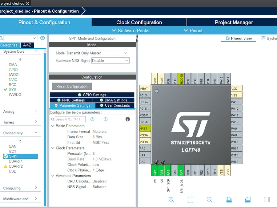
To kick off our project, we'll begin by configuring the STM32 microcontroller's SPI peripheral as a Transmit-only Master. This step is crucial for establishing communication between the microcontroller and the SSD1306 display.
Step One:- Open CubeMX & Create New Project Choose The Target MCU STM32F103C6 & Double-Click Its Name
- Go To The Clock Configuration & Set The System Clock To 8MHz
Configuration for the SPI Mode :
- In the Categories tab, select the SPI1 & Transmit Only Master
- In the clock parameters, set the prescaler to 8 to achieve a baud rate of 4.0 Mbits/s.
Configuration for the GPIO :
- Configure The GPIO Pin PA3(DC) as Output Pin
- Configure The GPIO Pin PA4 (CS) as Output Pin
- Generate The Initialization Code & Open The Project In CubeIDE
- Write The Application Layer Code
- Open Proteus & Create New Project and click next
- Click on Pick Device
- Search for STM32F103C6 & UG-2864HSWEG01
- Click on Terminal Mode then choose (DEFAULT & POWER &GROUND)
- finally make the circuit below and start the simulation
If you have any questions or suggestions don't hesitate to leave a comment below


Comments
Please log in or sign up to comment.