You can access the source code files via this link.
This project aims to teach you about the Serial Peripheral Interface (SPI) and how to interface Matrix LED 8x8 and 7-Segment Displays with an STM32 microcontroller using MAX7219 as the display driver. The article focuses on implementing the displays through the SPI communication protocol and simulating the project in Proteus software.
MAX7219:
MAX7219 is a popular display driver IC that simplifies the process of interfacing multiple displays with a microcontroller. It is designed to drive up to 64 individual LED segments or 8 digits of 7-segment displays. The IC handles the multiplexing and driving of the displays and uses SPI communication protocol to interface with the microcontroller.
Matrix LED Display:
A matrix LED display is a type of display that consists of a grid of LEDs arranged in rows and columns. Each LED can be individually controlled to display a specific pattern, character or symbol. Matrix LED displays are commonly used in digital signage, scoreboards, and outdoor displays due to their high brightness and visibility.
7-Segment Display:
A 7-segment display is a type of electronic display device that can display numbers and some letters using seven segments. Each segment can be controlled individually to display a specific number or letter. 7-segment displays are widely used in digital clocks, calculators, and other electronic devices where numeric output is required.
In this project, we will walk you through the process of interfacing the Matrix LED and 7-Segment Displays with the STM32 microcontroller using MAX7219 as the display driver and SPI communication protocol. We will also demonstrate how to simulate the project in Proteus software to verify the functionality of the system
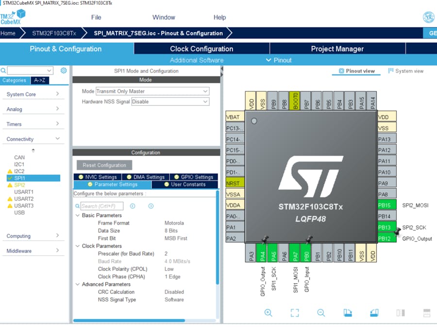
Step One:- Open CubeMX & Create New Project Choose The Target MCU STM32F103C6 & Double-Click Its Name
- Go To The Clock Configuration & Set The System Clock To 8MHz
- Configure The GPIO Pin PB0 as Output Pin
7 Segment Configuration:
- Configure The GPIO Pin PA4 as Output Pin (CSPin)
- In the Categories tab, select the SPI1 & Transmit Only Master
Matrix LED Configuration:
- Configure The GPIO Pin PB12 as Output Pin (CSPin)
- In the Categories tab, select the SPI2 & Transmit Only Master
- Generate The Initialization Code & Open The Project In CubeIDE
- Write The Application Layer Code
- Open Proteus & Create New Project and click next
- Click on Pick Device
- Search for STM32F103C8 & MAX7219 & MATRIX 8x8 RED & 7SEG_MPX8_CC_BLUE, RES
- Click on Terminal Mode then choose (DEFAULT & POWER &GROUND)
- finally make the circuit below and start the simulation
If you have any questions or suggestions don't hesitate to leave a comment below


Comments
Please log in or sign up to comment.