Agriculture is a major sector in countries such as China, India, Southern Africa and many more. Yet most developing countries fall back in generating the required annual yield, this causes inflation in prices due to higher demand.
I live in India where the agricultural sector holds the second spot in agricultural production in the world, which is 14% of India's GDP. Despite being the largest sector in India there is a fall in the contribution to the GDP. This fall of the agricultural sector is due to lack of technological improvements and proper farming methods.
Farmers tend to move on to other work sectors, since the farming practices are labor intensive and the lack of proper financial support, for tools and proper equipment. In India it is common to see news headlines of farmers committing suicide as they are not able to cope up to make a suitable living, as they are not able to meet the minimum demands.
With today's technology, we could replace and improve most the labor intensive tasks with automated systems. Especially with the advent of machine learning and 3D printing.
So I'm among a community of other students who are set to develop better tools and automated machines that could improve the current agricultural state.
In this project I'm going to document how to build a prototype of a robot that can analyze the soil and sow seeds. The objective of the project is building a prototype of a robot that can provide live data of the soil across a stretch of land and this data would be analysed and processed using a machine learning model to give suitable suggestions on the crops that can be grown in the patch of land.
Lets start with the list of hardware and tools required to build the project.
- STM32F407 Discovery Board
- HC-05 Bluetooth or any LORA Serial
- 2 x Servo
- 4 x Motors with PWM Driver
- Perfboard
- PCB
- Female/Male Header Pins
- 10k Resistor
- Power Bank 5V (Optional)
- Mini USB Cable
- LiPo Battery Pack with Charging Circuit.
Tools Required
- Soldering Iron
- 3d Printer
- Multimeter
- Logic Analyser (Optional)
At the heart of this project is a STM32F407 Discovery board, we will be using this board as it is compatible with AdACore and has the required hardware specifications in par with the project we are building. Here are some of the features of the board -
- STM32F407VGT6 microcontroller featuring 32-bit ARM Cortex-M4F core, 1MB Flash, 192KB RAM in an LQFP100 package
- On-board ST-LINK/V2 with selection mode switch to use the kit as a standalone STLINK/V2 (with SWD connector for programming and debugging)
- Board power supply: through USB bus or from an external 5 V supply voltage
- External application power supply: 3V and 5V LIS302DL, ST MEMS motion sensor, 3-axis digital output accelerometer MP45DT02, ST MEMS audio sensor, omnidirectional digital microphone CS43L22, audio DAC with integrated class D speaker driver
- Four user LEDs, LD3 (orange), LD4 (green), LD5 (red) and LD6 (blue)
- 2 USB OTG LEDs LD7 (green) VBus and LD8 (red) over-current
- Two push buttons (user and reset)
- USB OTG FS with micro-AB connector
- Extension header for all LQFP100 I/Os for quick connection to prototyping board and easy probing
For the communication I had planed to use a Long Range Serial Transceiver, but it was not delivered in time for this contest, so as an alternative I decided to use the HC-05 which is a Bluetooth serial module.
Block DiagramThe STM32F407 board controls the motors and the servos for direction, soil measurement and dropping seeds. The analog measurements are then converted to a JSON array and sent over Serial to the python server. I am using a python based server, because it is easier to perform machine learning as it has plenty of machine learning based libraries.
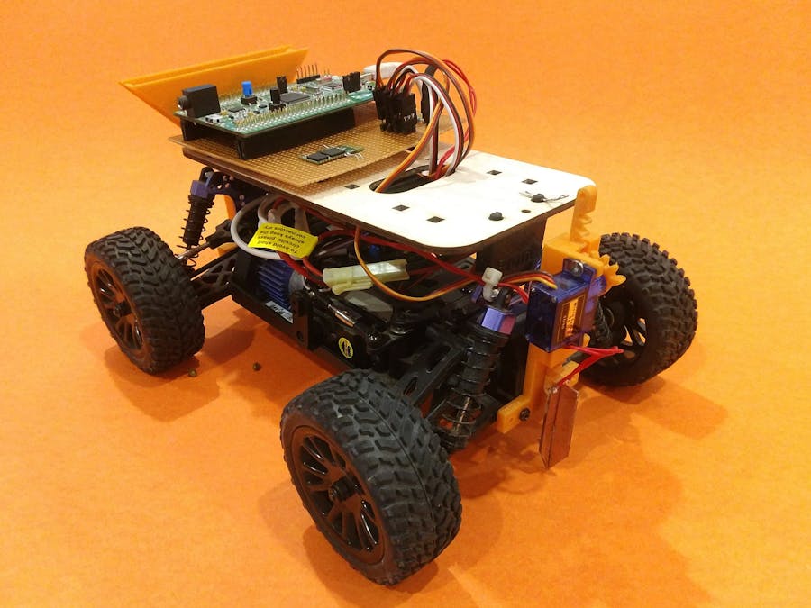
HardwareLet's start with building the hardware of the project, first we will be building the chassis for the robot. I decided to convert an RC based car chassis to be suitable for this project. The RC car comes with an in built motor driver which accepts two PWM signals one for the direction and the other for motion.
I designed the seed dropper and the measuring module, which also acts as the device which digs holes, in Autodesk fusion 360. The design requires two micro servos, one to control the seed flow and the other to control the motion of the measuring module.
I used a PCB cut out as seen in the picture to design the soil sensor, I used a rotary tool to cut the PCB to the dimensions and then soldered wires to both the plates of the soil sensor, these plates would check the conductivity of the soil which would intern map to the moisture level of the soil.
After designing the 3D parts I printed it using a 3D printer at 200mm layer height in PLA, the 3D printer I used was an Anet A8 set at 180 degree printing temperature.
After printing the two modules you need to, mount it to the front and rear of the chassis using the two screws. You can change the 3D design to match the mounting holes of your chassis, if you are using a different one, most chassis follow two screw type of mounting mechanism.
Once you got the 3D printed parts mounted, we need to attach the two micro servos, I glued the servo head to the gear head as seen in the picture and then mounted it on the main frame using the screws provided with the servos.
After all the 3D printed parts were mounted on the chassis, now it was time to measure the PWM signals we need to generate to control the motor speed and the direction.
The PWM signal for the motors had three states, one the initial resting state where the motors are still, another would be where the motors move in one direction and the next state is in the opposite direction. I used an oscilloscope and a signal generator to measure the states.
The directional servo had a similar three state configuration where the initial state would be straight, the next would be left and the last would be right.
Similarly, I measured the PWM signals required to control the servos of the 3D printed parts. All the servos require a PWM signal at 50Hz.
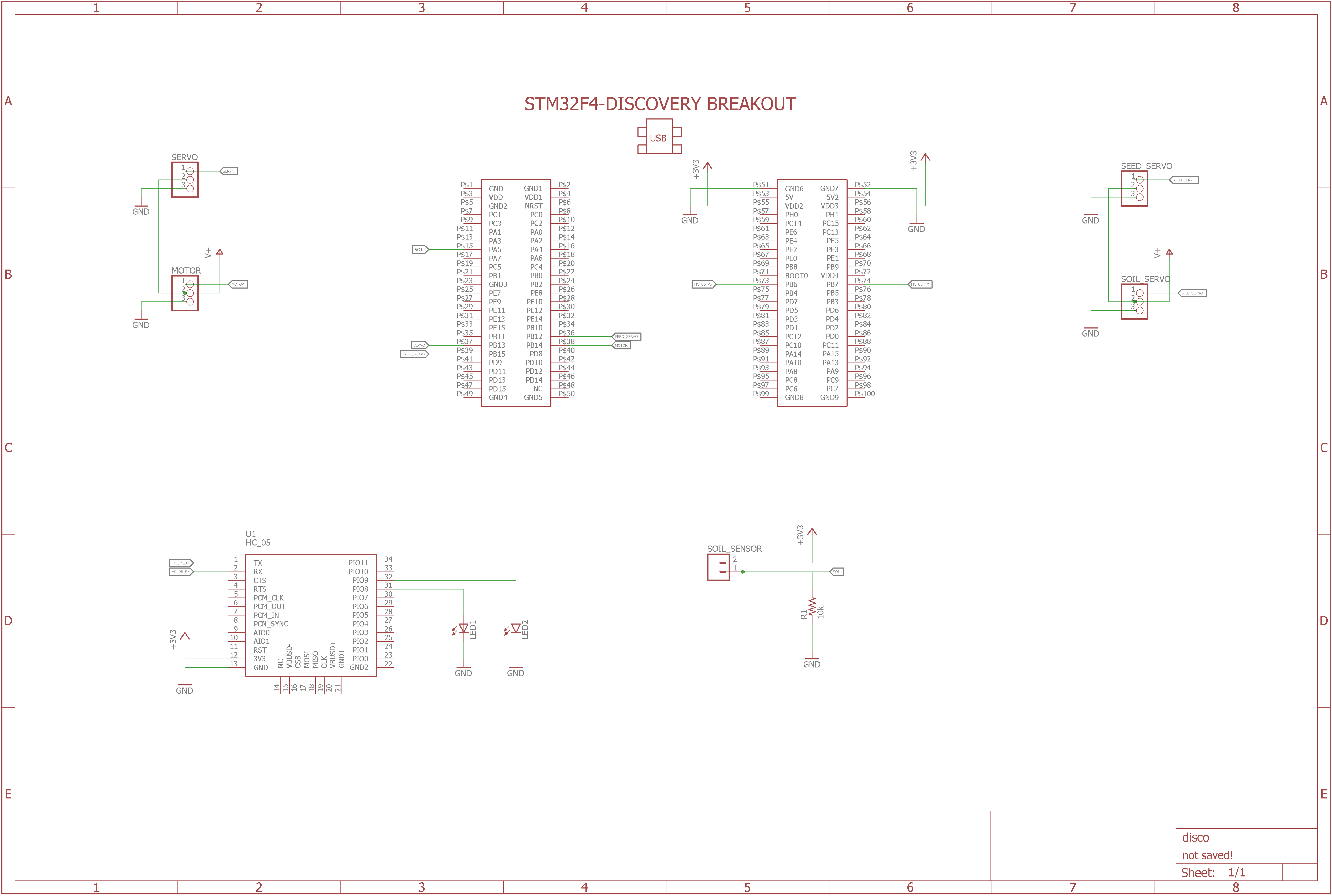
CircuitAfter building the chassis, the 3D printed parts and calculating the PWM duty cycle of all the servos and motor. I proceed to build the circuit. The circuit is as found in the picture above, I soldered all the components onto a perf board and used a 5V power bank to power the discovery board. The motors and servos were powered by a LiPo battery.
After completing the hardware it was now time to program the discovery board, I programmed the board using the Ada programming language. To get started with the programming you need to install the discovery board drivers and GPS IDE with GNAT Community Edition.
The code for this project can be found in the Github repository below. In the program I created three different subprograms.
The first subprogram is used to measure the analog voltage from Pin PA5 with the help of the inbuilt ADC.
The second subprogram provides us with the necessary procedures and functions to establish a serial communication, it contains procedure Serial_Print to send a string over serial to the python server (will contain analog measurements in the form of JSON) and Serial_Read which returns data sent from the python server.
The third subprogram is the control, where as the name implies, contains a list of procedures which control the robot, procedures include forward where the robot moves forward, plant_seed where the robot drops a seed and more.
The different PWM readings that you had measured earlier needs to be entered into the control.adb file, here you need to enter each of the values in terms of duty cycles.
The main program is where all the code comes together, here we have the analog conversion and the control sequence mapped to a character received over the serial communication. The baud rate for the serial communication is 115200, using USART1, with pins PB6 and PB7.
After you edit the code, now we need to upload the code on to the board. The discovery board has an inbuilt ST Link which makes programming the board simpler and you can you use any of the ST tool set to test or debug the board. You also need to install the necessary driver for the board, you can find the driver for the discovery board here.
Python Control / ML ServerTo start working with the python code you need to first install the necessary dependencies, to keep things organized I use Anaconda, which is a python tool to manage dependencies and environments. Make sure you have installed anaconda and open up an anaconda terminal window.
I have exported an environment.yml file, from which you can install all the dependencies in a single command.
conda env create -f environment.yml
The above command will create an environment "ada-robot", you can activate the environment by typing -
For linux
source activate ada-robot
For windows
activate ada-robot
After installing the dependencies and activating the environment you should see a terminal window as seen in the picture.
The python program is of two parts, one to control the robot and to generate the data for the machine learning model and the other is to use the data generated and run predictions based on the trained data.
The python control code first sets up a serial communication, make sure you edit your port number to match your port number. After establishing a serial communication the script then listens for key presses and links each key press to a character byte sent over serial.
When the 'f' key is pressed, the python script receives data from the robot with the measurements in the form of a JSON array, we then parse the JSON array and store the values in data.csv file.
For machine learning I am using python scikit-learn library, the data is imported and processed using pandas and numpy and finally trained using scikit-learn, for larger datasets, we can make use of Tensorflow instead of scikit-learn, as it supports complex models and even GPU support for faster training times.
Test RunTo test the robot, make sure you have connected the HC-05 to your computer and find the right serial port number, if you are on windows you can check this in the device manager.
After setup the connection, activate the anaconda environment that you created earlier and run the control.py file. Now you should be able to control your robot using the following commands
- "w" for forward,
- "s" for backward,
- "d" for right
- "a" for left
- "q" to drop a seed
- "e" to dig hole and perform measurements.
- "q" to stop
- "e" to face forward
To terminate the python program you need to hit the ESC key on your keyboard.


_9nsOFQ7ama.png?auto=compress%2Cformat&w=48&h=48&fit=fill&bg=ffffff)


Comments
Please log in or sign up to comment.